Overview of Mortise and Tenon Joints
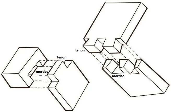
The mortise and tenon joint is a mechanical connection in which a projecting tongue (tenon) on one member fits into a corresponding cavity (mortise) in another member. It is widely used in woodworking for its combination of strength, geometric simplicity, and compatibility with solid wood movement.
In a typical configuration, the tenon is cut on the end of a rail or stretcher, while the mortise is cut into a post, leg, or stile. When properly proportioned and fitted, the joint resists tension, compression, shear, and racking forces without relying solely on metal fasteners.
Structural Principles and Load Behavior
The performance of a mortise and tenon joint depends on the way forces are transferred between the two connected members. Understanding the load paths clarifies why this joint is used in both fine furniture and heavy timber structures.
Compression and Bearing
Under vertical loads, such as in table legs or chair frames, the tenon shoulders bear directly on the face of the mortised member. This creates a large bearing surface that distributes compressive forces, reducing localized crushing of the fibers. Properly sized shoulders significantly increase resistance to racking and twisting.
Tension and Withdrawal Resistance
When a joint is loaded in tension along the axis of the tenon, withdrawal resistance is provided by friction, glue bond, and mechanical interlocks such as wedges or pins. A longer tenon with adequate glue surface and end restraint offers higher withdrawal capacity. In through-tenons, additional wedges or drawbored pegs can clamp the joint and prevent loosening.
Bending and Racking Forces
In frames subjected to lateral forces (for example, doors or chairs), mortise and tenon joints act as rigid frame corners. The stiffness is derived from:
- Tenon thickness and width, which control bending strength within the joint
- Shoulder depth, which resists rotations and racking
- Fit accuracy, which limits play and deflection under load
Proper proportioning ensures that failure occurs in the surrounding wood members instead of at the joint interface.
Shear and Rolling Shear
Shear stresses develop along the cheeks of the tenon and the walls of the mortise when the joint is loaded perpendicular to the tenon axis. Sufficient cheek area, accurate fit, and appropriate adhesive selection are critical. Grain direction is important: cross-grain shear capacity is typically lower than parallel-to-grain capacity, so joint layout must account for grain orientation in both members.
Key Components and Terminology
A mortise and tenon joint includes several defined surfaces and features. Consistent terminology is important for design, communication, and documentation.
| Element | Description | Functional Role |
|---|---|---|
| Mortise | Rectangular cavity cut into the receiving member | Provides housing and lateral support for the tenon; transfers shear and bearing loads |
| Tenon | Projecting tongue formed on the end of the mating member | Engages the mortise, transmits tension, compression, and bending forces |
| Shoulders | Step or ledge formed at the base of the tenon | Provides bearing surface, controls racking, conceals joint line |
| Cheeks | Large side faces of the tenon | Primary glue and bearing surfaces; carry shear and tension |
| Haunch | Additional small projection or extension on the tenon | Prevents twisting, supports narrow sections, preserves arrises |
| Wedge | Tapered insert driven into a kerf or slot | Expands tenon or locks joint mechanically, especially in through-tenons |
| Pin or Peg | Round or rectangular dowel through mortise and tenon | Prevents withdrawal; in drawboring, pulls joint tight |
Design Proportions and Technical Parameters
Effective joint design relies on proven dimensional relationships. These are typically expressed as ratios relative to the thickness or width of the joined members rather than fixed values, allowing adaptation to different stock sizes.
Tenon Thickness and Width
Common guidelines for tenon sizing in furniture and light structural work include:
- Tenon thickness: approximately one-third of the thickness of the mortised member (range 0.25–0.5 × member thickness).
- Tenon width: as large as practical but usually not more than 4–5 times the tenon thickness to limit risk of shear failure in the cheeks.
- For wide rails: double or twin tenons may be used instead of a single over-wide tenon.
For example, if the mortised member is 45 mm thick, a typical tenon thickness would be about 14–16 mm. For a 70 mm wide rail, the tenon might be 50–60 mm wide, leaving adequate shoulders at the top and bottom.
Tenon Length and Embedment
Tenon length determines the embedment depth and glue area. Typical ranges are:
For interior furniture frames:
Tenon length: approximately 0.5–0.75 × the width of the receiving member, with a usual range of 25–40 mm in chair and table frames.
For heavy timber framing:
Tenon length: often 75–150 mm or more, subject to member size and structural requirements. A common practice is to maintain at least 50–60 mm of solid wood beyond the end of the tenon in blind joints.
Shoulder Dimensions
Shoulders add stiffness and cover imperfections in the mortise. Important considerations include:
Shoulder width along the grain: generally 3–5 mm minimum to prevent splitting or crushing at the arrises, more in heavily loaded or visible joints.
Shoulder depth across the grain: sufficient to provide bearing and conceal the joint; often 3–10 mm depending on member size and design.
Clearances, Fit, and Tolerances
The functional fit for a mortise and tenon depends on construction method and adhesive:
Glue joint fit: a sliding or light hand-pressed fit is typically preferred. Excessively tight joints can scrape away adhesive or split the mortised member during assembly.
Typical tolerance ranges:
- Clearance on thickness (cheek fit): about 0.01–0.05 mm for high-precision work; up to 0.1 mm in general furniture construction.
- Clearance on width: usually tighter, aiming for full shoulder contact and minimal side play.
In structural timber framing where shrinkage is expected, slightly looser initial fits are sometimes used, with wedges or drawbored pegs taking up final slack.
Major Types of Mortise and Tenon Joints
Mortise and tenon joints can be adapted into many variants, each suited to specific functional and aesthetic requirements.
Through Mortise and Tenon
In a through mortise and tenon, the tenon passes completely through the mortised member and is visible on the opposite face. Features include:
Visual expression: the end grain of the tenon appears on the surface, which can be left flush, proud, or wedged for a decorative effect.
Inspection and maintenance: visible faces make inspection easier; wedges or pegs can be monitored or replaced if necessary.
Applications: exposed frame construction, visible furniture joints, and timber framing where wedge-locked joints are required.
Blind (Stub) Mortise and Tenon
A blind mortise and tenon does not pass completely through the mortised member. The tenon stops short of the opposite face, leaving a concealed joint. Characteristics include:
Invisible connection: no break in the visible surface, preferred for fine furniture and panel frames.
Reduced risk of breakout: the unpenetrated face remains intact, improving appearance and surface integrity.
Constraint: slightly reduced glue surface compared to a through tenon of the same member dimensions.
Haunched Mortise and Tenon
A haunched tenon has an additional projection or extension beyond the main tenon. Typical configurations are used at frame corners near the edge of a stile or rail:
Purpose of the haunch:
- Supports narrow sections at the frame edge and prevents cupping or twisting.
- Maintains a thin arris or groove, such as where a panel groove runs through the stile.
Common in door frames, window frames, and frame-and-panel construction where the rail meets the stile near the edge.
Wedged and Fox-Wedged Tenons
Wedged tenons introduce mechanical expansion to lock the joint.
Through-wedged tenon: the tenon projects through the mortise and has saw kerfs. After assembly, wedges are driven into these kerfs, expanding the tenon to clamp against the mortise walls.
Fox-wedged tenon: used in blind joints. Wedges are inserted in kerfs before assembly. When the joint is driven home, the wedges compress and then expand inside the mortise, locking the tenon. This technique requires precise layout and cannot be disassembled without destroying the joint.
Drawbored and Pinned Mortise and Tenon
In a pinned (or pegged) mortise and tenon, a dowel passes through both members to prevent withdrawal.
Drawbored configuration: the peg hole in the tenon is offset slightly relative to the corresponding holes in the mortised member. When the peg is driven, it pulls the joint tightly together, creating internal clamping forces even without glue.
Applications: traditional timber framing, chairs, and large frames where mechanical locking is required, or where assembly is performed before adhesives cure.
Specialized and Compound Tenons
For wide rails or large structural members, specialized tenon forms are used:
Double or twin tenons: two narrower tenons instead of one wide tenon, reducing risk of cross-grain shear failure and easing cutting.
Shouldered or housed tenons: where the tenon is combined with a shallow housing or dado in the mortised member, increasing bearing area and improving alignment.
Stub and relish designs: where the tenon is shorter or offset to preserve material at critical sections, important in structural timber design.
Material Selection and Wood Behavior
Material properties strongly influence joint performance, assembly, and long-term stability.
Species and Density
Species selection affects bearing strength, shear capacity, and resistance to wear:
Hardwoods such as oak, beech, ash, and maple offer high compressive and shear strength, making them suitable for heavily loaded joints and high-use furniture. Softwoods such as pine, fir, and spruce can be used effectively in larger cross-sections and in timber frames where member sizes compensate for lower material strength.
Moisture Content and Dimensional Change
Wood undergoes dimensional change with moisture variation, particularly across the grain. In a typical frame, the mortised member and tenoned member may change width and thickness differently over time.
Design considerations include:
- Allowing for cross-grain movement in wide rails and panels by sizing tenons and shoulders appropriately.
- Avoiding glue bonds that excessively restrain movement in wide components, which can lead to splitting.
- Selecting stable, conditioned stock with moisture content compatible with the service environment, often 6–10% for interior furniture and 12–18% for covered but unconditioned structures depending on climate.
Grain Orientation and Strength Direction
Grain direction affects the resistance of fibers to splitting, shear, and bearing:
Tenons are typically cut with the long dimension parallel to the grain for maximum strength in bending and tension. Mortises are positioned to avoid leaving thin short-grain sections at the edges or ends of the member that could split under assembly or service loads.
Joint Preparation and Cutting Techniques
Accurate joint geometry depends on methodical layout, controlled cutting, and careful fitting.
Layout and Marking
Consistent layout prevents accumulated errors across a frame or assembly. Standard practice includes:
Using a marking gauge from a single reference face on all members so the mortise and tenon align even if the board thickness varies slightly. Marking baseline shoulders on the tenoned member with a square to ensure parallel shoulders. Clearly marking waste areas on both the mortise and tenon to avoid cutting errors.
Hand Tool Methods
Traditional hand tool workflows typically proceed as follows:
Mortise cutting: using a mortise chisel to chop along the marked lines, working in stages from each side to full depth. Chips are removed progressively, maintaining vertical chisel alignment.
Tenon cutting: sawing the shoulders first with a backsaw, then the cheeks along the grain. Final fitting is done with a shoulder plane, router plane, or chisel to achieve a precise sliding fit.
This approach offers high control and is suitable for small batches and custom work.
Machine and Power Tool Methods
For larger production or repeated components, power tools and machines increase consistency and speed:
Mortises can be cut by hollow chisel mortisers, slot mortisers, plunge routers with jigs, or CNC routers. Tenons can be cut with tenoning jigs on table saws, dedicated tenoning machines, routers with templates, or CNC equipment.
Machine setups must account for safe clamping, controlled depth, and consistent reference faces to maintain repeatable alignment across multiple parts.
Adhesives and Mechanical Reinforcement
Mortise and tenon joints can function purely mechanically, but adhesives and reinforcements enhance strength and reliability in many applications.
Adhesive Options
Common adhesive systems include:
PVA (polyvinyl acetate) wood glue: widely used in furniture for its ease of use and adequate strength. Requires close-fitting joints and clamping.
Polyurethane glue: moisture-curing and gap-filling, useful where fit is less precise, but foaming must be controlled and squeeze-out removed.
Epoxy: high strength and good gap-filling properties, often used in exterior or marine applications, or where wood is degraded or irregular.
Animal (hide) glue: traditional reversible adhesive with good creep resistance, used in restoration and fine furniture.
Pins, Pegs, and Wedges
Mechanical reinforcement methods provide redundancy and assembly flexibility:
Pegs (round dowels or square pins): improve withdrawal resistance and allow assembly without continuous clamping pressure.
Wedges: used particularly with through and fox-wedged tenons to lock the joint and compensate for minor variances in mortise size.
In structurally significant joints, these reinforcements are placed away from high-stress short-grain regions to avoid splitting.
Furniture and Cabinetmaking Applications
Mortise and tenon joints are a core connection method in furniture frames, cabinets, and seating.
Chairs and Seating Frames
Chairs subject joints to cyclic and multi-directional loads, making mortise and tenon joints especially suitable at the junctions of legs, rails, and stretchers.
Common chair applications:
Front and back legs joined to rails with blind or through tenons. Side stretchers and cross stretchers connected with smaller tenons, sometimes pinned. Backrests and crest rails joined to rear legs using curved or angled tenons.
In seating, tenons are often elongated and sometimes double to handle bending loads from occupants leaning back or sideways.
Tables and Workbenches
Table frames use mortise and tenon joints at the intersection of legs and aprons. Workbenches often incorporate larger through or housed tenons for higher load capacity.
Typical configurations:
Leg-to-apron frame with blind tenons for interior furniture. Workbench bases with substantial through tenons pegged or wedged. Stretcher rails between legs using drawbored or pinned tenons to maintain rigidity.
Doors, Frames, and Panels
In frame-and-panel construction, mortise and tenon joints connect rails and stiles around a floating panel.
Applications include:
Cabinet doors with haunched or twin tenons at the corners to maintain alignment and prevent twist. Furniture carcass frames where front face frames are joined with mortise and tenon at each intersection. Room doors and shutters where long stiles and wide rails require haunched or double tenons for stability.
Cabinet Carcasses and Face Frames
Mortise and tenon joints connect face frames to cabinet bodies and corners of frame structures that support drawers and doors.
In solid wood carcasses, mortise and tenon joints provide reliable alignment and long-term performance, especially important for large cabinets with heavy doors or shelves.
Timber Framing and Structural Applications
In timber framing, mortise and tenon joints connect large structural members such as posts, beams, and braces.
Post and Beam Connections
Vertical posts and horizontal beams are commonly assembled using tenons on the beam ends entering mortises in the posts or tie beams.
Features include:
Large cross sections (often 100–300 mm or more) that allow robust tenon dimensions. Drawbored pegs that pull and lock the joints. Shoulders that transfer vertical loads and resist racking in the frame.
Braces and Diagonal Members
Diagonal braces limit racking and distribute loads in timber structures. Their ends are often connected using shorter tenons or housed mortise and tenon joints.
The braces transmit compression loads under lateral forces and may also carry tension under certain load combinations. Tenon proportions, housing depth, and peg placement are set to prevent splitting at the ends of braces.
Trusses and Roof Structures
Traditional roof trusses can be assembled with mortise and tenon joints at key intersections:
Tie beam to principal rafter with tenons or housed tenons. King post or queen post joints using multiple tenons and pegs.
These joints must be designed to transfer both gravity loads and wind loads without excessive deformation.
| Connection | Common Joint Type | Primary Load Type |
|---|---|---|
| Post to tie beam | Through or housed mortise and tenon, often pegged | Vertical compression, racking, some tension |
| Post to sill or base plate | Stub tenon or housed tenon | Vertical compression, uplift restraint |
| Diagonal brace to post/beam | Short tenon, sometimes housed | Compression under lateral loads |
| Rafter to tie beam or wall plate | Birdsmouth with tenon or housed tenon | Compression, shear, uplift |
Metal, Engineered Wood, and Hybrid Uses
While mortise and tenon is historically associated with solid wood, similar concepts apply to engineered and composite materials.
Engineered Wood Products
Materials such as LVL (laminated veneer lumber), glulam, and laminated panels can be joined with mortise and tenon variants if their internal structure and fastening requirements are considered.
Routing or machining mortises in engineered products must avoid weakening the laminations at critical zones. Adhesive compatibility and surface preparation (such as sanding away factory finishes at bonding areas) are important.
Metal and Wood Hybrid Joints
Metal components sometimes incorporate mortise and tenon-like features, or metal hardware is used to reinforce wooden joints.
Examples include:
Steel or aluminum plates with slots receiving timber tenons. Hidden steel reinforcement inside mortised regions, especially in high-load or seismic applications. Metal pegs or bolts passing through mortise and tenon joints for added capacity.
Common Issues and Practical Considerations
Effective use of mortise and tenon joints requires attention to potential complications in design, construction, and service.
Fit and Assembly Problems
Undersized tenons can lead to loose joints, reduced bearing area, and poor alignment. Oversized tenons risk splitting the mortised member during assembly, especially in dense hardwoods or when moisture content is not uniform.
To manage these risks, dry fitting is often performed before gluing or pegging, allowing minor corrections with planes or chisels.
Splitting and Short-Grain Failure
Improper mortise placement near the end or edge of a member can leave short-grain sections that are vulnerable to splitting during assembly or under load.
Preventive measures include:
Maintaining sufficient distance from ends and edges. Using haunches, housings, or widened shoulders. Orienting tenon shoulders so that forces are transmitted along the grain where possible.
Long-Term Stability and Creep
Over time, repeated loading and moisture variations can cause minor loosening or creep in joints. Adhesive selection, mechanical reinforcement, and correct proportioning reduce these effects.
In high-humidity environments or outdoor structures, additional sealing, protective finishes, and compatible exterior-grade adhesives help preserve joint integrity.
Basic Construction Workflow Example
While methods vary, a typical workflow for a rectangular blind mortise and tenon in furniture-scale work can be summarized as follows:
1) Planning and Layout
Determine joint location, member dimensions, and required tenon size based on structural and aesthetic requirements. Mark the mortise boundaries and corresponding tenon shoulders from a single reference face using a marking gauge and square.
2) Cutting the Mortise
Secure the mortised member firmly. Cut the mortise to depth using a chosen method (chisel, mortiser, or router), working to the layout lines. Ensure parallel walls, adequate depth, and a flat bottom for blind mortises when needed.
3) Forming the Tenon
Cut shoulders accurately to establish the final length of the tenon. Cut cheeks along the grain, aiming for a slightly oversized tenon. Refine the fit with hand tools, checking frequently against the mortise until a smooth sliding fit is achieved without forcing.
4) Assembly and Clamping
Apply adhesive to appropriate contact surfaces, insert the tenon into the mortise, and bring shoulders into firm contact. Use clamps to maintain pressure across the joint while adhesive cures, or install pegs/wedges as specified in the design. Remove squeeze-out and verify alignment during curing.
Conclusion
The mortise and tenon joint combines geometric simplicity with high mechanical performance, making it a primary connection method in furniture-making, architectural joinery, and timber framing. By understanding structural behavior, correct proportions, material characteristics, and execution techniques, practitioners can design and build joints that remain reliable and accurate over long service lives.