Overview of CNC Wood Machining
CNC wood machining uses computer numerical control to cut, drill, mill, carve, and engrave wood and wood‑based panels with high precision and repeatability. A CNC system interprets a program (typically G‑code) and drives motors on multiple axes to move a cutting tool relative to the workpiece.
Compared with manual woodworking, CNC machining enables accurate geometry, consistent quality in batches, tighter tolerances, complex contours, and efficient material utilization. It is widely used for cabinets, furniture, doors, decorative panels, signmaking, musical instruments, interior architecture components, and prototypes.
Types of CNC Woodworking Machines
CNC machines for wood differ in kinematics, rigidity, spindle configuration, and typical applications. Selecting the appropriate machine type is essential for process stability and productivity.
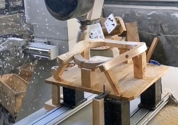
Gantry CNC Routers
Gantry routers are the most common CNC machines for wood. The spindle moves over a fixed table via a bridge (gantry). They are suited to panel processing and nested‑based manufacturing.
- Typical work envelope: 1200 × 2400 mm to 2100 × 4200 mm or larger
- Axes: 3 axes (X, Y, Z) standard; optional 4th / 5th axis for indexing or simultaneous motion
- Spindle power: ~3 kW for light work to 9–12 kW for production cutting
- Applications: cabinet components, doors, furniture parts, signs, 2D and 3D carving
CNC Machining Centers for Wood
CNC machining centers for wood often feature a moving table or moving column, enclosed structure, and integrated tool changers. They provide improved accuracy and faster toolchanging compared with basic routers.
These machines commonly include multi‑spindle drilling heads for line boring, grooving units, and saw units, enabling full processing of panels and solid wood components in one setup.
Pod and Rail Machines
Pod and rail CNCs support workpieces on vacuum pods mounted on rails, leaving the tool free to machine edges and faces without table interference. They are preferred for door frames, window components, shaped furniture parts, and operations requiring access to multiple sides.
The open under‑part access allows horizontal boring, mortising, and tenoning attachments. Precise pod positioning is critical for repeatability and collision avoidance.
CNC Lathes and Turning Centers for Wood
CNC wood lathes rotate the workpiece while tools cut profiles, grooves, and decorative patterns. Typical uses include stair balusters, chair legs, columns, and turned decorative parts.
Some machines integrate milling heads for fluting and patterning on the rotating part, and can combine turning with drilling and slotting in one cycle.
Specialized CNC Engravers and Carvers
Compact CNC engravers are used for signs, inlay work, 3D relief carving, and small decorative objects. They typically have smaller spindles and work envelopes but high positioning accuracy and fine step resolution for detailed features.
Wood and Wood‑Based Materials for CNC Machining
Different wood materials behave differently under cutting loads, affecting tool selection, cutting parameters, and achievable surface quality. Understanding material properties helps prevent burning, tear‑out, and dimensional instability.
Solid Wood
Solid wood offers attractive appearance and strength but is anisotropic and variable. Grain direction, density, and moisture content strongly influence machining behavior.
- Softwoods (e.g., pine, spruce): lower density, easier cutting, but prone to fuzzing and fiber tearing
- Hardwoods (e.g., oak, maple, beech, walnut): higher density, require sharper tools and controlled feed; can burn if feed is too low
- Moisture content: typically 8–12% for interior applications; higher moisture increases cutting forces and risk of dimensional change after machining
Cross‑grain machining and end grain cutting require attention to tool sharpness and support to avoid chipping and tear‑out.
Plywood and Laminated Panels
Plywood consists of cross‑laminated veneers bonded with adhesive. It machines relatively predictably but the glue lines increase tool wear. Edge chipping is a frequent concern.
Laminated panels (melamine‑faced chipboard, HPL‑laminated plywood, etc.) require tools and strategies that minimize chipping of the decorative layer, especially on the exit side of the cut.
MDF, HDF, and Particleboard
MDF and HDF have uniform density and are widely used in cabinet and furniture production. They are suitable for machining small features and 3D reliefs. However, they are abrasive, increasing tool wear, and fine dust levels are high, requiring effective extraction.
Particleboard has coarser chips and lower internal bond strength compared with MDF. Edge stability is lower, so machining parameters and tool geometry must account for reduced strength, especially in thin wall sections.
Engineered and Composite Wood Products
Engineered wood such as LVL, laminated beams, and wood‑plastic composites require specific tool geometries and cutting parameters due to glue lines or plastic contents. Tool coatings and carbide grades must be selected for abrasion resistance and heat control.
Fundamentals of CNC Wood Cutting
Wood cutting mechanics differ from metals due to fiber structure, lower softening temperature, and elastic behavior. Proper control of chip thickness, cutting edge geometry, and heat generation is necessary.
Chip Formation in Wood
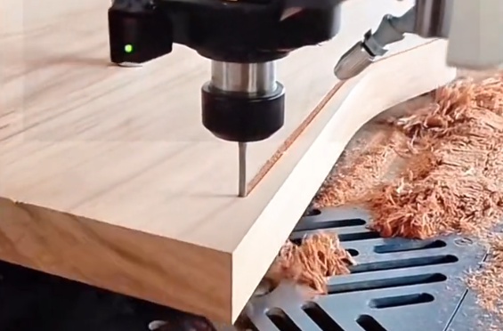
In wood, cutting can be viewed as controlled fiber separation. Chip formation is influenced by rake angle, clearance angle, cutting direction relative to grain, and support of the wood fibers. Excessive rubbing instead of cutting causes burning, poor surface quality, and tool wear.
Cutting Directions and Grain Orientation
Relative orientation of tool motion and wood grain affects surface finish and risk of tear‑out.
- With the grain (longitudinal cutting): smoother surface, lower forces
- Across the grain: higher risk of chipping at surface, especially on exit edge
- End grain: higher cutting forces; sharp tools and suitable chipload are crucial
Optimized toolpaths and climb vs conventional cutting strategies can reduce surface defects at critical edges.
Heat, Burning, and Tool Wear
Wood can burn at relatively low temperatures when friction is high. Causes include dull tools, too low feed rate, excessive spindle speed, or insufficient chip evacuation. Controlling heat through correct parameters and sharp tooling is essential for dimensional accuracy and tool life.
Tooling for CNC Wood Machining
Correct tool selection has direct impact on quality, throughput, and cost. Woodworking tools are typically solid carbide or carbide‑tipped due to abrasive wear mechanisms from fibers, adhesives, and fillers.
Routing and Milling Cutters
Common tool types for CNC routing include straight cutters, spiral end mills, compression bits, and profile tools. Selection depends on material, operation type, and required edge quality.
| Tool Type | Typical Diameter (mm) | Flute Geometry | Main Uses |
|---|---|---|---|
| Straight flute bit | 3–20 | Straight, 1–3 flutes | General slotting, pockets in softwood and MDF |
| Upcut spiral | 3–16 | Helical, upward chip evacuation | Grooves, pockets, deep slots; good chip removal |
| Downcut spiral | 3–16 | Helical, downward chip flow | Clean top edges in laminates, veneers, engraving |
| Compression spiral | 3–16 | Upcut at tip, downcut near shank | Chip‑free edges on both faces of laminated panels |
| Insert router cutter | 10–25 | Replaceable carbide inserts | High‑volume panel cutting, improved tool life |
Drills and Boring Tools
CNC machining centers use dedicated boring bits for dowel holes, line boring, and hinge cup holes. Brad‑point and through‑hole drills are common, often in multi‑spindle boring heads for rapid drilling patterns in panels.
Saws and Grooving Cutters
Saw blades mounted on CNC units produce straight cuts and grooves. They are used for scoring decorative surfaces, sizing operations, and cutting deep grooves where router bits are less efficient.
Engraving, V‑Bits, and 3D Carving Tools
Engraving tools with small tip diameters and V‑bits with defined angles (e.g., 60°, 90°) are used for lettering, inlays, and chamfers. Ball nose end mills (e.g., 3–12 mm) are common for 3D relief carving and sculptured surfaces.
Tool Materials and Coatings
Solid carbide tools provide rigidity and wear resistance for wood. Carbide grades with abrasion resistance are preferred for MDF and laminated boards. Coatings can reduce friction and heat but must be compatible with the woodworking application.
Workholding and Fixturing for Wood
Stable and repeatable workholding is required to maintain tolerances and avoid vibration. Wood is lighter and often more flexible than metals, so clamping must secure the part without causing deformation or marking visible surfaces.
Vacuum Tables
Vacuum tables are common in panel processing. A vacuum pump draws air through a grid and porous spoilboard or through gasketed zones, securing the panel to the table surface.
Key considerations:
- Sufficient vacuum flow and pressure for large and small parts
- Use of spoilboards (e.g., MDF) for cut‑through operations
- Zoning and masking to maintain holding force when machining small components
Pods, Clamps, and Mechanical Fixtures
Vacuum pods and mechanical clamps are used when edge access is required or for smaller parts. Pods can elevate parts to allow full edge machining. Proper layout prevents interference between tools and clamps.
Sacrificial Boards and Nesting Strategies
Spoilboards protect the machine table and allow complete cut‑through. In nested‑based manufacturing, parts of various shapes are arranged on a full sheet to minimize waste, then cut in a single program. Part bridges or tabs may be left to maintain vacuum holding until the end of the cycle.
Feeds, Speeds, and Machining Parameters
Feeds and speeds for wood are typically higher than for metals, but wood is more sensitive to excessive heat and vibration. Parameters must be adjusted to material, tool type, tool diameter, and cutting depth.
Spindle Speed
Typical spindle speeds for wood range from 12,000 to 24,000 rpm, depending on tool diameter and material. Larger diameter tools generally require lower rpm to keep the cutting edge speed within recommended limits.
Feed Rate and Chipload
Feed rate determines chipload (chip thickness per tooth), which must be maintained within a suitable range. Too low chipload causes rubbing and burning; too high chipload causes tool overload, deflection, and potential breakage.
| Tool Diameter | Material | Typical Chipload per Tooth |
|---|---|---|
| 3–6 mm | MDF / plywood | 0.05–0.15 mm |
| 6–10 mm | MDF / particleboard | 0.10–0.25 mm |
| 10–16 mm | MDF / particleboard / softwood | 0.20–0.40 mm |
| 6–12 mm | Hardwood | 0.08–0.20 mm |
Depth of Cut and Step‑Over
Depth of cut is limited by tool stiffness, available power, and material behavior. For slotting in MDF with a 6–8 mm bit, full‑depth cutting in a single pass may be feasible if chipload and machine rigidity are adequate. For harder woods and larger tools, multiple passes may be necessary to maintain edge quality and reduce load.
Step‑over in pocketing and 3D machining is typically set between 30% and 60% of tool diameter. Lower step‑over improves surface finish but increases cycle time.
Ramp, Plunge, and Entry Strategies
Wood responds better to ramping or helical entry rather than straight vertical plunges, which can generate heat and stress on the tool. Entry strategies also help reduce edge chipping and visible marks at the start and end of toolpaths.
Toolpath Strategies for Wood Components
Toolpath generation influences cycle time, surface quality, and tool life. CAM software provides various strategies suited to profiling, pocketing, drilling, and 3D machining of wood.
Profiling and Contour Cutting
Profiling cuts define the outer shape of parts. When cutting laminated panels, path compensation and climb vs conventional cutting can be chosen to achieve clean edges on the visible side. Lead‑ins and lead‑outs reduce tool marks at entry and exit.
Pocketing and Slotting
Pocketing clears material inside closed boundaries. Efficient pocketing strategies minimize tool engagement peaks and avoid sudden changes in direction that can cause vibration or tool deflection in wood panels.
Nesting for Panel Processing
Nesting arranges part geometries within a sheet to optimize yield. CAM software can manage common‑line cutting, tabs, and micro‑joints to keep parts stable during machining while minimizing trimming operations after cutting.
3D Relief Machining and Finishing Passes
3D relief machining uses roughing passes to remove bulk material followed by finishing passes with smaller tools or ball nose cutters. Roughing typically uses larger step‑over and higher depths of cut, while finishing uses reduced step‑over to achieve fine surface quality.
CNC Programming and Data Flow
Reliable CNC wood machining requires a controlled data flow from design to finished part. This includes CAD modeling, CAM programming, post‑processing, and program management at the machine.
CAD Models and Design Considerations
Designs may originate from parametric CAD, specialized furniture design software, or 2D drawing tools. Wood‑specific design parameters include grain orientation, joinery details, hardware positions, clearances for assembly, and allowance for edge banding.
CAM Setup and Post‑Processing
CAM systems define tool libraries, machining operations, and toolpaths. Post‑processors convert the CAM output into G‑code and machine‑specific instructions, including tool calls, spindle speed commands, and coordinate system settings.
Program Management on the CNC
CNC control systems manage part programs, tool offsets, and work coordinate systems. Consistent naming, revision control, and backup procedures help maintain reliable production.
Accuracy, Tolerances, and Quality Control
Wood is dimensionally sensitive to humidity and stress relief, so achievable tolerances differ from metals. However, CNC machining can produce consistent fits suitable for joinery, hardware, and assembly.
Machine Calibration and Compensation
Machine accuracy depends on proper calibration of axes, ball screws or rack‑and‑pinion systems, and compensation tables. Regular checks of squareness, backlash, and scale factors are necessary for maintaining dimensional consistency.
Measurement Techniques for Wood Parts
Quality control typically uses calipers, tape measures, and templates for larger components, and gauges for hardware positions. Due to wood movement, measurements should be taken under stable environmental conditions.
Managing Dimensional Stability of Wood
Wood movement due to moisture changes can affect part fit after machining. Controlled storage, acclimatization before machining, and appropriate design allowances reduce dimensional variation in service.
Dust Extraction and Chip Management
Wood machining generates chips and fine dust that affect air quality, surface cleanliness, and machine reliability. Effective dust extraction is necessary for health, safety, and process stability.
Dust Collection Systems
CNC routers require dust hoods, flexible hoses, and ducting connected to a dust collector with adequate airflow. Proper design minimizes buildup on tools and workpieces and helps maintain clear visibility of the cutting area.
Health and Safety Considerations of Wood Dust
Fine wood dust can be harmful if inhaled. Extraction, filtration, housekeeping, and personal protective equipment help reduce exposure. Certain woods have specific sensitizing or allergenic properties, so material data and safety recommendations should be followed.
Common Issues and Process Considerations
Several recurring issues can affect CNC wood machining, leading to scrap, rework, or additional finishing effort. Systematic parameter adjustment and consistent tooling practices help mitigate these problems.
Surface Tear‑Out and Chipping
Tear‑out often occurs at exit edges when machining across the grain or in veneered and laminated materials. Strategies include using compression bits, adjusting feed direction, optimizing chipload, and providing backup material at edges.
Burn Marks and Poor Edge Quality
Burning is associated with excessive friction. Corrective actions include increasing feed rate within chipload limits, reducing spindle speed, ensuring tool sharpness, and avoiding prolonged dwell at one position.
Tool Life and Wear in Abrasive Materials
MDF and laminated boards contain abrasive fillers and adhesives that shorten tool life. Using suitable carbide grades, appropriate coatings, and controlled cutting parameters can improve tool life and reduce edge degradation.
Safety Practices in CNC Wood Machining
CNC wood machinery combines high‑speed spindles, moving axes, and cutting tools. Safe operation depends on correct procedures, guarding, and awareness of machine status.
Machine Safeguards and Interlocks
Guarding, emergency stop buttons, and interlocks limit access to hazardous areas during operation. Safety systems should be checked regularly to ensure proper function.
Operational Safety and Setup Procedures
Safe work practices include verifying tool clamping, confirming workholding, checking programs with dry runs when appropriate, and using correct personal protective equipment. Operators should be trained in machine operation, alarm handling, and emergency procedures.
Applications of CNC Wood Machining
CNC technology is integrated throughout multiple wood product sectors due to its repeatability and flexibility. Consistent machining data enables predictable assembly and finishing.
Cabinet and Furniture Components
Panel cutting, drilling patterns for hardware, dowel holes, and pocketing for joinery are standard CNC operations in cabinet and furniture manufacturing. Nested‑based machining combines these in a single setup to produce ready‑to‑assemble parts.
Doors, Windows, and Architectural Elements
CNC routers and pod and rail machines are used for profiling, panel routing, and hardware pockets in doors and windows. Architectural elements such as moldings, wall panels, and column claddings use contouring and 3D relief machining.
Signmaking, Inlays, and Artistic Components
Engraving, V‑carving, and inlay pockets in solid wood or engineered boards are common. CNC control allows precise repetition of patterns and fonts, simplifying production of consistent signage and decorative pieces.
Planning a CNC Wood Machining Workflow
Effective CNC wood machining combines machine capability, tooling, workholding, programming, and inspection into a coordinated workflow. This includes planning stock sizes, nesting strategies, tool libraries, and quality control checkpoints.
Process Sequence and Routing
Typical process sequences may include rough panel sizing, CNC nesting and machining, edge banding, secondary machining for edges and hardware, assembly, and finishing. Clear routing plans minimize handling and reduce risk of damage.
Documentation and Standardization
Standardized tooling lists, setup sheets, and parameter libraries help maintain consistency across shifts and operators. Documented settings for common materials and tools support rapid troubleshooting and repeatable performance.
Summary
CNC wood machining combines high‑speed cutting, material knowledge, tooling selection, and controlled programming to produce accurate, repeatable wood components. By understanding machine types, materials, parameters, and workflow organization, users can achieve stable processes and reliable product quality.