Fundamental Types of Wood Machining Methods
Wood machining covers all mechanical processes used to change the size, shape, or surface quality of wood and wood-based products. Choosing the right method requires understanding the main process groups and their technical characteristics.
| Method | Main Purpose | Typical Accuracy Range | Surface Quality |
|---|---|---|---|
| Sawing | Primary cutting, sizing | ±0.5–2.0 mm | Rough to medium |
| Planing / Thicknessing | Flattening, dimensioning | ±0.1–0.5 mm | Smooth |
| Milling / Routing | Shaping profiles, contours | ±0.05–0.5 mm | Medium to smooth |
| Turning | Rotational shapes | ±0.1–0.5 mm | Smooth |
| Drilling / Boring | Holes, dowel locations | ±0.05–0.3 mm (position) | Medium |
| Mortising / Tenoning | Joints | ±0.1–0.4 mm | Medium |
| Sanding | Surface finishing | N/A (shape not primary) | Smooth to very smooth |
| Laser / Waterjet (for some panels) | Fine cutting, intricate shapes | ±0.02–0.2 mm | Very smooth edge (material-dependent) |
In practice, production often integrates several of these methods in sequence, from rough sizing to final finishing.
Key Factors That Determine the Machining Method
Systematic selection starts from clearly defined technical requirements. The following factors usually govern the choice of method and specific machine setup.
Wood Species and Material Type
Wood machining behavior depends strongly on species and product form:
- Solid softwoods (e.g., pine, spruce): generally easier to machine; allow higher feed speeds.
- Solid hardwoods (e.g., oak, beech, maple): denser and often abrasive; require sharper tools, lower feed speeds, and more stable machines.
- Engineered panels (MDF, particleboard, plywood): may contain adhesives and mineral fillers; increase tool wear and demand suitable cutter materials.
Key material properties influencing method selection include density, grain structure, presence of knots, moisture content, and dimensional stability. For example, highly knotty softwood stock may favor robust circular sawing and planing operations rather than fine milling in early process stages.
Dimensional Accuracy Requirements
Target tolerances define the necessary machining precision:
- Rough sizing: building lumber, non-visual framing components, crates — tolerances up to ±2 mm are typically acceptable; sawing and basic planing are sufficient.
- Furniture and cabinetry parts: often require ±0.1–0.3 mm dimensional accuracy; call for well-tuned planers, jointers, thicknessers, and CNC routers or precision milling machines.
- Precision joinery and assembly-critical components: dowel holes, mortise locations, and reference surfaces may demand ±0.05–0.1 mm; CNC machining, line boring machines, and carefully calibrated jigs become important.
When required tolerances approach the limit of a method’s capability, processes with higher stiffness (shorter tool overhang, rigid clamping, slower feed) and lower tool wear sensitivity are preferred.
Surface Quality and Finish Requirements
Desired surface quality strongly influences method choice:
Planing and milling can achieve smooth surfaces ready for fine sanding when cutting parameters and knives are optimized. For visible furniture surfaces, machining strategies aim to minimize tear-out and tooling marks in order to reduce subsequent sanding time.
Sanding is selected when a refined surface is needed for staining or high-quality coatings. Coarser machining marks or raised grain demand more aggressive sanding sequences (e.g., belt sanding followed by orbital sanding), while high-quality planed surfaces may only require light fine-grit sanding.
Workpiece Geometry and Complexity
Shape and geometry dictate which methods are feasible:
Linear edges and flat surfaces are efficiently processed by saws, planers, jointers, and wide-belt sanders. Profiles, grooves, and curved contours require routing or milling, either on manual spindle molders or CNC routers.
Cylindrical or rotationally symmetric parts (balusters, chair legs, knobs) are naturally suited to turning. Intricate, thin-walled geometries and fine internal cutouts may justify laser cutting or specialized CNC routing strategies with small-diameter tools.
Production Volume and Batch Size
Production scale affects both the method and the level of process automation:
Single-piece or small batch production favors flexible methods with quick setup, such as table saws, band saws, manual routing, and stand-alone planers. For high-volume production, dedicated machinery, multi-spindle setups, and CNC systems become more economical because setup time is spread over large quantities.
Methods with fixed tooling and automated feed systems (throughfeed moulders, CNC machining centers with automatic tool changers) are typically chosen for mass production of standardized components.
Tooling, Machine Capability, and Budget
Machine availability and investment constraints narrow down practical choices. Large CNC routers or throughfeed moulders provide extensive capability but require substantial capital and technical know-how. Small workshops often rely on multi-purpose machines (e.g., combination machines with sawing, planing, and mortising functions), which may limit achievable productivity but still can deliver good accuracy and surface quality with proper setup.
Safety, Noise, and Dust Control
For most wood machining operations, dust extraction and operator safety are mandatory considerations. Methods producing fine dust (sanding, CNC routing of MDF) require more robust extraction systems. Processes involving rotating tools at high speed (routers, shapers) demand careful attention to guarding, tool balance, and secure clamping. These aspects may lead to choosing one method over another when multiple options can technically achieve the same geometry.
Machining Solid Wood vs Wood-Based Panels
The choice of method differs significantly between solid wood and engineered wood products.
Solid Wood Machining Characteristics
Solid wood presents anisotropic behavior due to grain direction, earlywood/latewood contrasts, and natural defects. Typical constraints include:
Machining with the grain generally yields better surfaces and reduced tear-out, so planing and routing are often oriented accordingly. End grain machining is more challenging; it often requires sharper tools, reduced feed, and sometimes different cutting geometries.
For solid wood, sawing and planing dominate early stages. Jointing surfaces for edge-gluing or reference faces is often achieved via jointers and thickness planers. Milling and routing are then used for profiling and joinery. Final surfaces normally receive sanding, especially on visible faces.
Panel Products Machining Characteristics
Panels such as MDF, particleboard, plywood, and laminated boards respond differently:
MDF and particleboard have homogeneous or near-homogeneous cores but can be abrasive due to adhesives and fillers. They machine uniformly but wear tools more quickly. Panel saws and CNC routers equipped with carbide or diamond-tipped tooling are common choices.
Plywood requires careful attention to veneer orientation, as cross-laminated layers may cause splintering at edges. Methods with scoring blades or climb-cutting strategies at edges can reduce edge defects. Laminated and coated panels often call for specialized saw blades or cutters designed to minimize chipping of decorative surfaces.
Sawing Methods and When to Use Them
Sawing is typically the first step in converting raw lumber or panels into workable pieces. Selecting the appropriate sawing method affects yield, accuracy, and surface condition.
Circular Sawing
Circular saws (table saws, panel saws, rip saws) are widely used for straight cuts. They offer good productivity and moderate accuracy suitable for most rough-to-medium precision requirements.
Key parameters include blade diameter, tooth count, hook angle, kerf width, and rotational speed. For ripping solid wood, blades with fewer, larger teeth and positive hook angles are preferred to evacuate chips efficiently. For crosscutting and panel cutting, higher tooth counts and modified tooth geometries provide smoother edges.
Band Sawing
Band saws use a continuous flexible blade, enabling curved cuts and deep resawing. They excel in situations requiring efficient material use, such as slicing veneers or resawing thick stock into thinner boards.
Band saws generally leave a rougher surface compared with finely tuned circular saws. They are often followed by planing or sanding. For precise work, careful blade selection (width, tooth pitch), proper tensioning, and well-aligned guides are important.
Panel Sawing
For sheet materials, sliding table saws or vertical panel saws provide accurate, repeatable cuts with support over large areas. When cutting veneered or laminated panels, scoring blades or special tooth geometries help prevent edge chipping.
Planing, Jointing, and Thicknessing
Planing operations define flatness, parallelism, and final thickness. These methods are essential for producing reference surfaces used in subsequent machining.
Surface Planing and Jointing
Surface planers and jointers create one flat reference face and one straight, square reference edge. This is vital for accurate assembly, gluing, and further machining.
Knives in the cutterhead remove material in a continuous pass, with depth of cut typically in the range of 0.5–3.0 mm depending on machine power and wood species. For tear-out-prone woods, a smaller depth of cut and higher knife sharpness are beneficial. Helical or spiral cutterheads with staggered inserts can further improve surface quality.
Thickness Planing
Thickness planers produce boards of uniform thickness by referencing off the planed face. In precision work, they are often preceded by jointing to ensure flatness.
When selecting this method, considerations include maximum width, feeding mechanism, and achievable tolerance. Correct machine setup (parallel infeed/outfeed tables, calibrated thickness scale) is essential for consistent results.
Milling and Routing of Wood
Milling and routing are used for shaping edges, cutting grooves and profiles, and producing complex 2D and 3D geometries.
Spindle Moulders and Routers
Spindle moulders (shapers) and handheld or table-mounted routers operate with rotating cutters. They are versatile tools for edge profiles, rebates, grooves, tongue-and-groove joints, and raised panels.
Tooling choices range from simple straight cutters to complex profile heads and multi-part cutter stacks. Important variables include spindle speed, feed rate, and cutter diameter. Higher spindle speeds with appropriate feed rates can improve surface finish, as long as cutting forces remain within safe limits.
CNC Routing and Milling
CNC routers add numerical control, allowing precise, repeatable machining of intricate shapes, nested parts, and drilling patterns. They are especially effective for panel processing and component production requiring many repetitive operations.
Key selection aspects for CNC routing include working area size, spindle power, tool changer capacity, vacuum or mechanical workholding, and software capability. For small shops, shared or outsourced CNC services can provide high-precision machining without full in-house investment.
Turning for Cylindrical and Rotational Parts
Woodturning is used to produce cylindrical or rotationally symmetric components such as spindles, chair legs, table legs, and knobs.
Manual Turning
On manual lathes, the operator guides cutting tools to shape the rotating workpiece. This method is flexible and suitable for small to medium batch sizes where customization or artistic variation is required.
Tool selection (gouges, skews, parting tools) and spindle speed are matched to workpiece diameter and wood species. Proper tool support and sharpness are important for smooth surfaces and safety.
Copy and CNC Lathes
Copy lathes use templates to reproduce the same shape repeatedly, while CNC lathes follow programmed toolpaths. These machines are chosen when consistency and productivity on standardized turned components are required.
Drilling, Boring, and Jointing Operations
Holes and slots for mechanical fasteners and wood joints must be positioned accurately to ensure assembly quality.
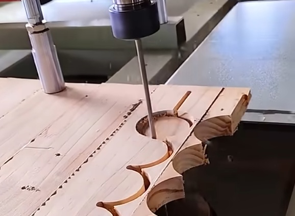
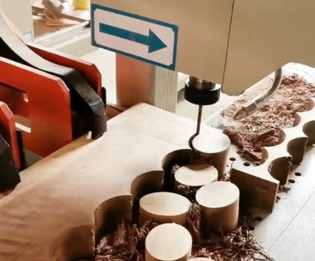
Drilling and Boring Methods
Standard drill presses and handheld drills serve for low-volume, less critical applications. For higher precision and throughput, line boring machines, multi-spindle boring units, and CNC drilling centers are used.
Bit types (brad-point, Forstner, auger, carbide-tipped) are selected based on hole diameter, depth, and material. For example, Forstner bits create flat-bottomed holes at moderate speeds and are often used in furniture production.
Mortising and Tenoning
Mortise and tenon joints require precise matching of cavity and projection. Dedicated mortising machines (chisel mortisers, chain mortisers) produce rectangular slots, while tenoning machines or specialized cutter heads on spindle moulders produce tenons.
When tolerances are tight, CNC routers or dedicated CNC joinery machines can create highly accurate mortises and tenons, as well as other advanced joint geometries.
Sanding and Surface Preparation
Sanding improves surface quality, prepares wood for finishing, and removes machining marks.
Types of Sanding Methods
Common sanding methods include handheld sanding (orbital, random orbit), belt sanding, edge sanding, and wide-belt sanding for panels. Wide-belt sanders are chosen for high-volume, uniform panel finishing, while orbital sanders offer flexibility and control for detailed surfaces and curved parts.
Grit progression is selected according to initial surface roughness and final finish requirements. Coarse grits (e.g., 60–80) are used to remove heavy marks, followed by finer grits (120–220 or higher) to produce a smooth surface. Excessive sanding can alter part dimensions, so process planning must consider stock allowance.
Selection of Cutting Tools and Materials
Tool material and geometry have a direct impact on machining quality, tool life, and economic efficiency.
Tool Materials
Common cutting tool materials in wood machining include high-speed steel (HSS), carbide-tipped tools (HW), and polycrystalline diamond (PCD) tools. HSS offers high sharpness and good edge quality, but limited wear resistance, suitable for softer woods and low-volume work.
Carbide is more wear-resistant and better for abrasive materials like panel products. PCD tools provide maximum tool life in large-scale panel and composite machining but involve higher initial costs and more specialized sharpening services.
Tool Geometry and Cutting Parameters
Rake angle, clearance angle, cutting edge radius, and chip gullet design determine chip formation and surface quality. Positive rake angles reduce cutting forces, beneficial for softer woods, while neutral or slightly negative rake angles can improve tool life in abrasive materials.
Cutting speed (related to spindle RPM and tool diameter), feed rate, and depth of cut must be coordinated to avoid burning, tear-out, or excessive tool wear. Manufacturers’ recommendations and empirical testing are commonly used to refine these parameters.
Machine Capability, Workholding, and Fixturing
Even when a machining method is technically suitable, the actual machine and fixturing must support the required precision and productivity.
Machine Rigidity and Accuracy
Machine stiffness affects dimensional accuracy and surface quality. Heavy, well-built machines with rigid frames, stable bearings, and precise feed mechanisms can maintain tighter tolerances and reduce vibration-related defects.
Feed systems (manual, mechanical, or servo-driven) influence repeatability and surface consistency. In high-accuracy applications, backlash, table flatness, and alignment of guides and fences become critical factors.
Workholding and Clamping
Secure workholding prevents movement during machining and reduces the risk of kickback or chatter. Depending on the method, clamping solutions include mechanical clamps, vises, jigs, fixtures, and vacuum tables.
For CNC routing of panels, vacuum systems provide efficient holding without obstructing the toolpath. For irregular solid wood shapes, custom jigs are often required to position reference faces and edges consistently.
Process Sequencing and Combination of Methods
Choosing the right method is not limited to single operations; it also involves defining an efficient sequence that meets quality targets with minimal waste and time.
Typical Process Chains
A common workflow for solid-wood furniture components may follow this sequence: rough sawing, jointing and thicknessing, secondary cutting and shaping via sawing and routing, drilling and joinery cutting, and finally sanding and surface finishing.
Panel-based production might start with panel sawing or CNC nest cutting, followed by edge banding, drilling or boring operations, then fine sanding of visible surfaces.
Balancing Roughing and Finishing Steps
Roughing operations remove the majority of material quickly but leave higher surface roughness and possible minor deviations. Finishing operations employ smaller depths of cut and refined parameters to achieve final dimensions and surface quality.
Planning adequate allowance for finishing (stock to be removed) ensures that machining marks and minor defects are eliminated without overshooting target dimensions.
Technical Considerations and Common Issues
When selecting methods, it is helpful to anticipate common issues and align them with process capability.
Accuracy and Alignment Issues
Misalignment of fences, guides, and machine tables can cause cumulative dimensional errors. Regular calibration and periodic checking of squareness and parallelism are necessary. When extremely tight tolerances are required, CNC methods and reference surfaces machined in the same setup help reduce error stacking.
Surface Defects and Tear-Out
Tear-out, fuzzing, and burn marks arise from inappropriate cutting parameters, dull tools, or unfavorable grain direction. Methods that allow adjusting cutting angles or employing shear-cutting (such as spiral heads or climb-cutting under controlled conditions) can reduce these defects.
Tool Wear and Maintenance
Abrasion from resins, adhesives, and fillers can quickly degrade cutting edges. Tool choice and regular sharpening intervals must match production volume and material. Monitoring surface quality and cutting forces is a practical way to determine when tools require maintenance.
Method Selection by Application
Different end uses call for different balances of speed, cost, accuracy, and surface quality. The following table summarizes typical method choices for common applications.
| Application | Preferred Methods | Primary Criteria |
|---|---|---|
| Construction Lumber | Sawing, planing | High throughput, moderate accuracy, robust processing |
| Cabinet Panels | Panel sawing or CNC nesting, edge machining, boring, sanding | Dimensional accuracy, edge quality, efficient nesting |
| Solid-Wood Furniture Parts | Sawing, jointing, thicknessing, routing/milling, drilling, sanding | Fit accuracy, visual surface quality, stable joints |
| Decorative Profiles and Moldings | Moulders, spindle moulders, CNC routers | Profile consistency, high surface quality, volume capability |
| Turned Components | Manual or CNC turning | Shape precision, repeatability, smooth surface |
| Prototype or Custom Work | Flexible handheld and bench machines, small CNC | Versatility, minimal setup time, acceptable precision |
Structured Approach to Selecting a Wood Machining Method
A systematic selection process helps align methods with technical and practical requirements. The following steps can be applied to most projects:
1) Define Technical Requirements
Specify acceptable tolerances, surface quality, and joint fit requirements. Include information on wood species, moisture content, and final use conditions. This step clarifies whether general-purpose methods are sufficient or higher-precision machining is necessary.
2) Analyze Geometry and Production Volume
Determine the complexity of shapes, minimum feature sizes, and expected batch sizes. For simple rectangular parts in large numbers, dedicated saws and moulders may be optimal. For diverse, complex geometries, CNC routing or flexible multi-purpose machines are more suitable.
3) Match Methods to Capability and Resources
Compare the needed accuracy and surface quality with the capabilities of available machines. Where gaps exist, consider outsourcing, investment in new machinery, or process adjustments, such as adding finishing passes or improved fixturing.
4) Optimize Tooling and Cutting Parameters
Select tool materials and geometries appropriate to the material and required life. Use recommended cutting speeds and feeds as a baseline and refine them based on trial runs and observed results. Ensure that dust extraction and safety systems match the chosen methods.
5) Validate the Process with Samples
Before full-scale production, machine representative samples and verify all critical dimensions, fits, and surface qualities. Adjust operations and sequencing as needed. This validation step helps prevent systematic defects in larger batches.
Conclusion
Choosing the right wood machining method requires a structured evaluation of material properties, geometric complexity, accuracy and surface requirements, production volume, and available resources. Sawing, planing, milling, routing, turning, drilling, jointing, and sanding each solve different parts of the overall task, and most projects depend on a well-designed combination of these methods.
By defining requirements, understanding the technical capabilities of each process, and carefully planning tooling, fixturing, and process sequences, it is possible to achieve consistent quality, efficient material use, and reliable production results across a wide range of wood machining applications.