CNC wood milling is a computer-controlled subtractive manufacturing process that removes material from wooden workpieces using rotating cutting tools. It is widely used for furniture components, architectural elements, fixtures, patterns, molds, and specialized industrial parts that must meet repeatable dimensional and surface quality requirements.
Fundamentals of CNC Wood Milling
CNC wood milling uses programmed toolpaths to control the motion of a spindle with cutting tools along multiple axes. The process transforms digital models into physical parts by selectively removing wood from a solid blank, board, or panel.
A typical CNC wood milling system consists of:
- Mechanical structure (frame, gantry, linear guides, bearings)
- Drive system (stepper or servo motors, ball screws, rack-and-pinion drives)
- Spindle (motor, tool holder, collet system)
- Control system (CNC controller, motion control boards, drives)
- Software chain (CAD, CAM, G-code sender or integrated controller interface)
In operation, the user prepares a CAD model, generates CAM toolpaths, exports G-code, sets up the workpiece and tools, and runs the program. The CNC controller interprets G-code and coordinates axis movements and spindle speed to achieve the required geometry.
Key Benefits of CNC Wood Milling
CNC wood milling offers practical and measurable advantages over manual woodworking and simple template-based routing.
Productivity and Throughput
Automated toolpaths and continuous operation allow large quantities of identical parts to be produced with minimal operator intervention. Once a program is validated, the same job can be repeated on demand, enabling efficient batch production and just-in-time manufacturing.
Multi-axis motion and automatic tool changes reduce setup time between operations, so multiple features such as pockets, profiles, drilled holes, and surface contours can be completed in a single clamping.
Dimensional Consistency and Repeatability
CNC machines follow programmed paths with high positional accuracy, resulting in consistent dimensions and fit between mating parts. This is important in system furniture, cabinet components, structural joinery, and modular wooden assemblies.
Repeatability ensures that parts manufactured in different runs at different times maintain the same geometry, supporting replacement parts, spare components, and long-term product lines.
Complex Geometry and 3D Shaping
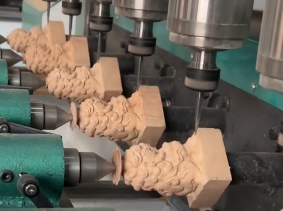
CNC milling can produce profiles, recesses, 3D surfaces, and compound curves that are difficult or impractical to achieve manually or with jigs. Multi-axis machines can access undercuts, angled faces, and complex transitions in a single setup.
This capability extends from decorative elements such as carvings and relief panels to functional forms such as ergonomic handles, contoured seats, and precisely shaped molds for composite parts or thermoforming.
Material Utilization and Waste Reduction
Optimized nesting layouts for sheet and panel materials reduce offcuts. Toolpaths can be programmed to minimize unnecessary passes, reduce air cutting, and use efficient entry/exit strategies. As a result, more parts can be cut from the same amount of material with predictable yields.
Process Control and Documentation
Digital workflows preserve machining parameters, tool lists, and setup instructions. This documentation supports quality control, traceability, and process standardization. Changes to product designs are implemented by updating digital files rather than reworking physical templates or guides.
Typical Applications of CNC Wood Milling
CNC wood milling is applied across many sectors where wood and wood-based materials are used in structural, functional, or aesthetic roles.
Furniture Manufacturing
In furniture production, CNC wood milling is used for:
- Cabinet parts (sides, shelves, backs, doors) with holes, dadoes, rabbets, and pockets
- Chair and table components with contoured shapes and joinery features
- Solid wood panel machining for tabletops and countertops
- Fixture, jig, and press components to support downstream assembly
Tight control of hole positions, tenon dimensions, and surface geometry supports efficient assembly and standardized hardware interfaces.
Architectural Woodwork and Interior Components
CNC milling enables precise fabrication of architectural and interior elements such as:
Wall panels, ceiling features, door and window components, balusters, handrails, and stair components can be produced with uniform geometry. This improves fit during site installation and simplifies coordination with other trades such as glass, metal, and mechanical systems.
Cabinetry, Closets, and Built-In Storage
Modular cabinet systems and custom built-in storage units use repetitive drilling patterns for hardware and precise panel cutting. CNC wood milling handles:
Systematic drilling patterns maintain compatibility with a wide range of hinges, drawer slides, shelf supports, and fasteners, enabling efficient assembly and serviceability.
Doors, Windows, and Frames
Wooden doors and windows require tight dimensional tolerances to ensure proper operation and weather sealing. CNC milling can machine:
Consistent profiles ensure that replacement parts and additional units match existing installations. This is relevant in large commercial projects and standardized product lines.
Pattern Making, Molds, and Jigs
Wood, plywood, MDF, and tooling boards are commonly used for patterns, molds, and fixtures. CNC wood milling creates:
Because digital models are used, modifications to geometry can be implemented quickly, and multiple versions of a pattern or mold can be produced from the same data set for testing and evaluation.
Musical Instruments and Specialty Products
CNC milling is applied to parts of musical instruments such as guitar bodies and necks, keyboard components, and wind instrument bodies made from wood. It is also used for specialty products like cutting boards, tool handles, sports equipment components, and precision wooden mechanisms.
How CNC Wood Milling Works in Practice
The workflow from design to finished wooden part involves several technical steps and process decisions.
CAD Modeling
The part geometry is designed in CAD software as 2D drawings, 2.5D features (contours and pockets), or fully 3D solids and surfaces. Design considerations include minimum feature sizes, wall thicknesses, tool access, and joinery geometry compatible with the planned milling process.
CAM Programming and Toolpath Strategies
CAM software converts CAD geometry into machining toolpaths and G-code. Common toolpath types for wood include:
Parameters such as stepdown, stepover, feed rate, spindle speed, and entry strategies are selected according to material type, tool diameter, and desired surface quality.
Machine Setup and Workholding
Securing the workpiece is critical to maintain accuracy and prevent vibration. Workholding methods for wood include:
The coordinate system is defined using work offsets. The operator sets the X, Y origin based on a corner or feature of the part, and Z based on the top of the stock or the machine table, depending on the programming approach.
Tool Selection and Spindle Parameters
Wood machining requires appropriate tool geometry and spindle speeds. Considerations include:
Spindle speed and feed rates are chosen to maintain chip load within recommended ranges for each tool and material combination, avoiding excessive heat and preserving cutting edge life.
Execution, Monitoring, and Inspection
During machining, the operator monitors:
After machining, dimensions and surface quality are inspected. Critical features may be measured with calipers, gauges, or coordinate measuring equipment to verify that tolerances have been met.
Machine Types for CNC Wood Milling
Different machine architectures are used depending on part size, complexity, and throughput requirements.
Fixed-Table and Moving-Gantry Routers
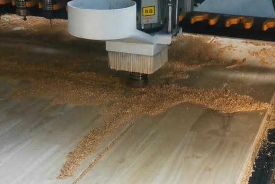
These are common in woodworking. The workpiece is fixed on a table while the gantry moves in X and Y and the spindle moves in Z. They are suited to large sheets and panels, such as plywood, MDF, and particle board, as well as smaller solid wood parts.
Moving-Table Machines
In these machines, the table moves in one axis and the gantry or column in another. They often offer high rigidity and are used where both accuracy and throughput are important, such as in large furniture and architectural component manufacturing.
3-Axis, 4-Axis, and 5-Axis Configurations
Axis count influences the complexity of geometries that can be machined.
| Machine Type | Axes | Typical Workpiece Size | Typical Applications |
|---|---|---|---|
| 3-axis router (gantry) | X, Y, Z | Panels and boards | Cabinet parts, flat panels, 2.5D reliefs |
| 3-axis machining center | X, Y, Z | Medium-sized blocks | Furniture parts, fixtures, small molds |
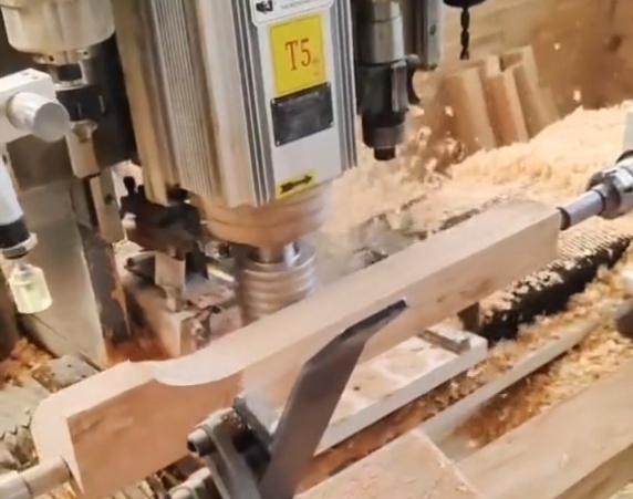
| 4-axis router with rotary axis | X, Y, Z, A or B | Long or rotational parts | Columns, balusters, chair legs, handles |
| 5-axis router | X, Y, Z, two rotary axes | Large 3D forms | Complex molds, sculpted surfaces, ergonomic components |
Materials Used in CNC Wood Milling
CNC milling can process a range of solid wood species and engineered wood products. Material characteristics influence tool selection, cutting parameters, and achievable surface quality.
Solid Wood
Common species include softwoods such as pine, spruce, and fir, and hardwoods such as oak, maple, beech, walnut, ash, and birch. Properties such as density, grain direction, and moisture content affect cutting behavior.
In milling solid wood, it is important to account for grain direction to reduce tear-out and splintering, especially on cross-grain cuts and exit edges. Sharp tools and suitable climb or conventional cutting strategies are selected based on the material and machine stability.
Engineered Wood and Panel Products
Engineered materials used in CNC wood milling include:
These materials are widely used in furniture and interior applications, so toolpaths and cutting parameters are often standardized for common board sizes and thicknesses.
Specialty Wood-Based Materials
High-density fiberboards, laminated veneer lumber, phenolic-faced plywood, and specialty tooling boards may be used for patterns, jigs, or high stability components. These materials can have higher abrasiveness and may require coated tools and adjusted cutting parameters.
Accuracy in CNC Wood Milling
Accuracy in CNC wood milling is influenced by machine capabilities, tooling, process parameters, and the physical characteristics of wood. It is useful to distinguish between machine accuracy, process accuracy, and functional accuracy of the finished part under real conditions.
Machine Positioning and Repeatability
Machine manufacturers specify positioning accuracy and repeatability for each axis, often in millimeters or micrometers over a defined travel length. Industrial CNC routers can reach positioning accuracies on the order of ±0.05 mm to ±0.1 mm under controlled conditions, while heavier machining centers may achieve finer levels.
However, wood is less dimensionally stable than metals, so achieving extremely tight tolerances in the final part must account for material behavior and environmental conditions.
Factors Affecting Accuracy in Wood
Wood is anisotropic and hygroscopic, meaning its properties vary with direction and moisture content. Key influences include:
As a result, the effective dimensional accuracy of wooden parts is typically managed within ranges that consider both machining precision and expected in-service dimensional change.
Typical Tolerances for CNC-Machined Wood Parts
Tolerances for wooden components vary by application. General guidance is summarized below.
| Feature Type | Typical Tolerance Range | Comments |
|---|---|---|
| Overall length/width of panel | ±0.2 mm to ±0.5 mm | Depends on sheet size, machine, and material stability |
| Hole centers for hardware | ±0.1 mm to ±0.3 mm | Critical for hinge alignment and drawer hardware |
| Joinery dimensions (tenons, dados) | ±0.1 mm to ±0.3 mm | Adjusted for fit and allowance for glue and swelling |
| Surface profile depth (2.5D) | ±0.2 mm to ±0.4 mm | Affected by tool wear and Z-axis calibration |
| 3D contoured surfaces | ±0.3 mm to ±0.8 mm | High-detail work may use closer tolerances with stable materials |
Surface Quality and Finish
Surface quality is linked to accuracy because excessive tear-out, ridges, or chatter requires additional sanding or rework. Factors influencing surface finish include:
Proper selection of tools and parameters can minimize sanding requirements, especially for visible surfaces and parts that must align flush with other components.
Process Parameters and Technical Considerations
To obtain reliable accuracy and surface quality, critical process parameters must be set appropriately for the specific wood material, machine, and tooling.
Feed Rate and Spindle Speed
The combination of feed rate and spindle speed determines chip load, cutting temperature, and tool life. Typical spindle speeds for wood range from approximately 12,000 rpm to 24,000 rpm, depending on tool diameter and material. Feed rates can range from a few meters per minute for fine detail to tens of meters per minute for roughing and panel processing.
Maintaining an appropriate chip load reduces friction and heat, lowers the risk of burning, and improves edge quality. Underfeeding at high spindle speeds can cause rubbing, while excessive feed with low spindle speeds can overload the tool.
Depth of Cut and Stepover
Depth of cut is selected based on tool diameter, material hardness, and machine rigidity. For slotting and deep pockets, multiple passes may be used to limit radial and axial loads. Stepover (sideways engagement) is adjusted to balance material removal rate and surface finish. Smaller stepover increases surface quality at the cost of longer cycle time.
Toolpath Direction and Strategy
Climb milling and conventional milling behave differently in wood, especially relative to grain direction. Climb milling can reduce tear-out in some situations but may be more sensitive to workpiece holding and machine rigidity. CAM strategies such as trochoidal milling, adaptive clearing, and finishing passes are applied to control cutting forces and surface quality.
Tool Wear and Tool Management
Wood and engineered boards can be abrasive, especially when containing resins or mineral fillers. Tool wear degrades accuracy and surface quality. Regular inspection and scheduled replacement of tools are essential, and some operations use tool length measurement systems and tool life management within the CNC controller.
Workholding and Fixturing for Wood
Stable workholding is essential to preserve dimensional accuracy and avoid vibration. Because wood is relatively light and can deform under clamping forces, fixturing is tailored to material and part geometry.
Vacuum Tables and Pods
Vacuum tables with gasketed zones hold flat panels for nesting operations. Vacuum pods and rail systems support solid wood and smaller parts. Proper sealing, clean filters, and adequate vacuum pump capacity are necessary to maintain holding force during aggressive machining.
Mechanical Clamping and Auxiliary Fixtures
Mechanical clamps, toggle clamps, and custom fixtures are used when vacuum is not feasible or when parts have complex shapes. Fixtures may incorporate locating pins, stops, and reference surfaces to ensure repeatable positioning and alignment. Fixture design must allow tool access without interference while supporting the part at points that minimize deflection.
Programming and Workflow Efficiency
Beyond machine hardware, process efficiency depends on how digital data is managed, from design to nested production.
Part Libraries and Parametric Designs
Standardized parametric models allow rapid adjustment of part dimensions and features without redesigning from scratch. For example, cabinet components can be defined by height, width, depth, and thickness parameters, with hardware hole patterns generated automatically. This supports consistent quality and reduces programming errors.
Nesting and Batch Production
For panel-based manufacturing, nesting software arranges individual parts on standard board sizes to minimize waste. Nesting strategies consider grain direction, part orientation, and toolpath optimization. Efficient nesting supports high utilization of materials and reduces handling.
Post-Processing and G-Code Management
Post-processors convert CAM toolpaths into G-code formatted for specific machine controllers. Consistent naming, revision control, and backup strategies help maintain a reliable library of programs. This is important when multiple machines or sites must produce identical parts from shared digital assets.
Quality Control of CNC-Milled Wood Parts
Systematic quality control ensures that the benefits of CNC wood milling translate into reliable products.
Dimensional Verification
Critical dimensions such as hole positions, joint widths, and overall lengths are checked using gauges, calipers, or coordinate measurement tools. Sampling frequency depends on production volume and process stability.
Fit and Assembly Checks
Where parts interact with hardware or other components, test assemblies can detect deviations that might not appear in simple dimensional checks. Functional tests verify that doors open and close correctly, drawers align smoothly, and architectural elements fit together on site.
Surface and Edge Inspection
Visual and tactile inspection identifies tear-out, burn marks, chatter, and tool marks. Standardized acceptance criteria guide decisions on rework or adjustment of process parameters.
Considerations and Practical Constraints
CNC wood milling offers significant advantages, but practical constraints should be considered in planning and operation.
Material Variability
Natural wood varies in density, grain structure, and moisture content even within a single board. This variability can cause local differences in cutting behavior and minor dimensional deviations. Process settings may require adjustment for different batches or species.
Environmental Conditions
Temperature and humidity changes can cause wood to expand or contract after machining. Production planning may allow for acclimatization of materials before machining, and tolerances are selected with expected in-service conditions in mind.
Chip and Dust Management
CNC wood milling generates large volumes of chips and fine dust. Effective extraction systems maintain visibility, protect machine components, and help maintain dimensional accuracy by preventing chip recutting and buildup on surfaces. Dust control also supports a safer working environment.
Best Practices for Reliable CNC Wood Milling
Implementing structured procedures improves process stability and final part quality.
Standardization of Tooling and Parameters
Maintaining standardized tool sets and parameter libraries for common materials reduces setup time and risk of errors. Cutting data can be refined over time based on actual results, tool life, and quality feedback.
Preventive Maintenance
Regular maintenance of linear guides, ball screws, drive systems, and vacuum equipment preserves machine accuracy. Scheduled checks and calibration routines minimize drift and unexpected downtime.
Documentation and Training
Clear documentation for setups, tool lists, and quality criteria helps operators run jobs consistently. Training in CAD, CAM, and machine operation ensures that programming decisions and on-machine adjustments support the desired accuracy and finish.
CNC wood milling provides a structured, repeatable, and precise method for producing wooden components in a wide range of applications. By controlling material selection, process parameters, machine condition, and quality checks, manufacturers can achieve reliable dimensional accuracy, high surface quality, and efficient throughput in both small-batch and large-scale production.