Wood milling is the controlled removal of material from wood or wood-based panels using rotary cutting tools. It includes shaping, profiling, slotting, surfacing, and contouring operations performed with manual or CNC machines. Understanding processes, tools, parameters, and costs is essential for accurate, efficient, and repeatable woodworking in both small shops and industrial production.
Fundamentals of Wood Milling
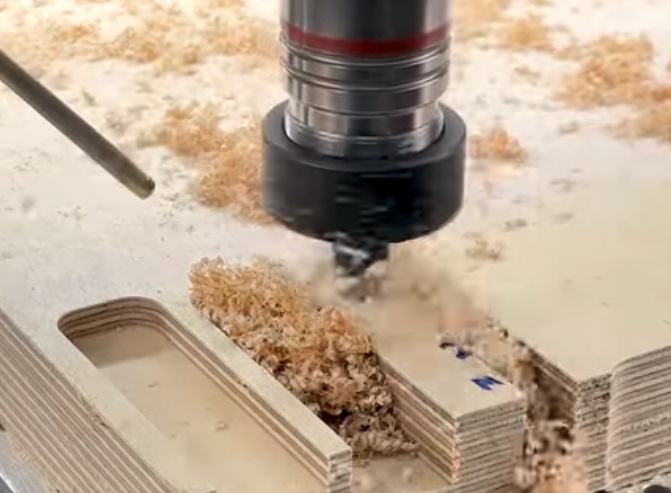
Wood milling relies on rotating cutters with multiple cutting edges that remove material as they pass through the workpiece. Milling can be done on solid wood, plywood, MDF, particleboard, and engineered panels, with adjustments to tooling and parameters according to material type.
Key characteristics of wood milling compared with metal milling include higher cutting speeds, lower cutting forces, fiber direction sensitivity, and higher dust and chip volume. The goal is to achieve desired dimensions, surface quality, and edge detail while controlling heat, tear-out, and tool wear.
Types of Wood Milling Processes
Wood milling covers a wide range of operations, from heavy stock removal to fine detailing. Grouping processes by purpose helps in choosing correct tools and settings.
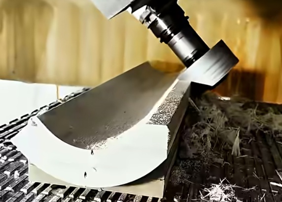
Face Milling and Surfacing
Face milling or surfacing generates flat, level surfaces on boards, panels, or glued-up slabs. It is commonly used to:
- Flatten rough-sawn lumber and slabs
- Plane glued panels to uniform thickness
- Prepare reference surfaces for joinery or CNC work
Face milling can be done using wide cutters on CNC routers, overhead routers, or spindle moulders. Larger diameter cutters and multiple cutting edges improve surface finish and productivity when properly balanced and aligned.
Peripheral Milling, Profiling, and Edge Shaping
Peripheral milling uses the outer diameter of the cutter to shape edges and external profiles. Typical tasks include:
- Roundovers, chamfers, and bevels
- Decorative moldings and frames
- Edge joint preparation and straightening
Profile cutters, router bits, and shaper heads produce repeatable shapes according to knife geometry. Correct feed direction and workpiece support are critical to avoid chatter and tear-out on the edge.
Slotting, Grooving, and Pocketing
Slotting and grooving remove material inside the workpiece to create slots, dados, channels, and internal pockets. Applications include shelf dados, panel grooves, mortises, cable channels, and hardware recesses. Slot width depends on cutter diameter or stack configuration, and depth is controlled by incremental passes to maintain reasonable cutting loads.
Drilling, Boring, and Hinge Machining
Drilling and boring operations produce holes for dowels, screws, and hardware. Dedicated line boring machines, combination CNC drilling centers, or CNC routers with multiple spindles are used in cabinet production for adjustable shelves and knock-down fittings. Hinge boring heads produce accurate, repeatable cup holes for concealed hinges, often in a single cycle with alignment pins.
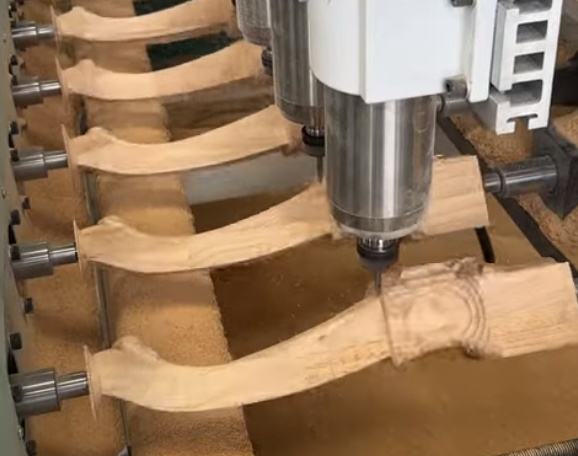
Contour Milling and 3D Shaping
Contour milling uses CNC-controlled motion to create 2D and 3D shapes, patterns, and reliefs. Typical operations include:
• Cutting nested cabinet parts from sheet goods
• Machining curved furniture components
• Carving relief panels and 3D surfaces
3D milling requires suitable toolpaths, ball-nose or tapered cutters, and appropriate step-over values to balance surface quality and machining time. Complex geometry places higher demands on fixturing and dust collection.
Tenoning, Mortising, and Joinery Milling
Mechanical joinery often involves specialized milling operations. Tenoning machines, slot mortisers, and CNC routers produce mortise-and-tenon joints, dowel holes, biscuit slots, and other structural connections. Dimensional accuracy and repeatability directly affect assembly quality, fit, and long-term joint performance.
Materials and Their Milling Characteristics
Wood and wood-based materials vary significantly in density, fiber structure, and adhesive content, all of which affect milling behavior, tool selection, and expected tool life.
Softwood and Hardwood
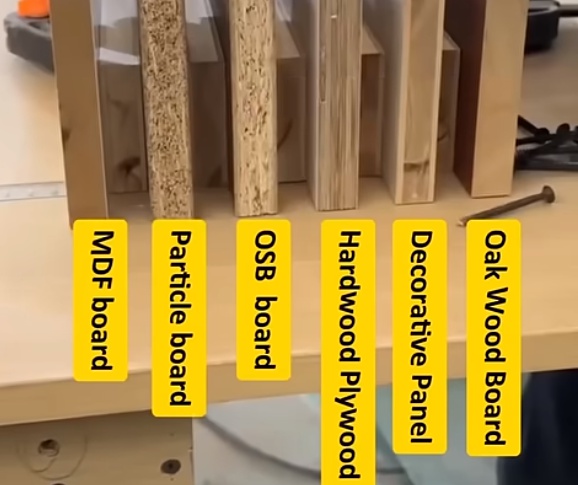
Softwoods (such as pine, spruce, and fir) are generally easier to mill but may contain knots, resin pockets, and pronounced grain contrasts. Hardwoods (such as oak, maple, beech, and walnut) offer higher density and strength but can cause greater tool wear and require more power. Interlocked or highly figured grain increases risk of tear-out, particularly when climb cutting is not used.
Plywood, MDF, and Particleboard
Panel products introduce resin binders and layered or particulate structures. Plywood can cause alternating grain directions at each veneer layer, while MDF and particleboard contain fine or coarse particles bound with resin. These materials are abrasive and may contain impurities, which accelerates tool wear and calls for robust cutter materials and coatings.
Engineered and Specialty Materials
Engineered products such as high-pressure laminates on substrates, veneer-laminated panels, and composite cores require careful parameter selection. Hard surface layers need high-quality edges to prevent chipping, and substrate density has to be considered to avoid delamination or poor edge integrity.
Wood Milling Machines and Equipment
Wood milling operations can be performed with handheld tools or stationary machines, from basic routers to multi-axis CNC centers. Selection depends on production volume, precision requirements, and part complexity.
Handheld Routers and Trimmers
Handheld routers and compact trimmers are widely used in small shops and on-site work. They are suitable for edge profiling, small grooves, hinge recesses, and template-based routing. Their flexibility is counterbalanced by higher dependence on operator skill and limitations in production throughput.
Router Tables and Spindle Moulders
Router tables extend the usefulness of handheld routers by mounting them inverted in a table. This allows better control over small workpieces and repeatable setups using fences and stops. Spindle moulders (shapers) are heavier-duty stationary machines with larger spindles, higher power, and interchangeable tooling systems, suitable for larger profiles, production runs, and heavier cuts.
CNC Routers and Machining Centers
CNC routers provide programmable control of toolpaths and automatic changes of tools, enabling high accuracy, repeatability, and complex shapes. Typical configurations include:
• 3-axis routers for panel processing, contouring, and pockets
• 4-axis routers for angled cuts and rotary work on columns or turned parts
• 5-axis machining centers for complex 3D surfaces and undercuts
Features such as vacuum tables, automatic tool changers, and integrated drilling heads increase productivity in cabinet, furniture, and architectural component production.
Planers, Jointers, and Thicknessers
While not always classified as milling in a metalworking sense, planers, jointers, and thicknessers are rotary cutting machines that remove material to create flat and parallel surfaces. Helical cutterheads with segmented inserts are increasingly common, offering lower noise, improved surface quality, and easier maintenance than traditional straight knives for many operations.
Combination Machines and Line Equipment
In production environments, milling is integrated into automated lines including:
• Edge banding machines with pre-milling units
• Throughfeed moulders for multi-face profiling in a single pass
• CNC nesting lines combining routing, drilling, and labeling
These systems are optimized for throughput and minimal manual handling, with infeed and outfeed conveyors, automatic positioning, and integrated dust collection.
Milling Cutters and Tooling for Wood
Milling cutters for wood are available in numerous geometries, body materials, and cutting edge materials. Careful tool selection directly affects cut quality, tool life, and cost per part.
Common Cutter Types
Typical cutters and bits used in wood milling include:
• Straight and spiral end mills
• Compression, upcut, and downcut router bits
• Profile cutters for moldings and edge details
• Slotting cutters and groovers
• Face milling heads and surfacing cutters
Tool diameter and flute length define achievable depth of cut and minimum inside radius. The number of flutes influences chip evacuation, feed rate capability, and surface finish.
Tool Materials and Coatings
Tool body materials include solid carbide, carbide-tipped steel, and high-speed steel. Solid carbide tools are rigid and wear-resistant, suitable for high-speed CNC operations and abrasive panel products. Carbide-tipped tools on steel bodies are versatile and cost-effective for many spindle moulder and saw applications. Coatings such as TiAlN and diamond-like coatings are sometimes used to extend life in high-wear situations, especially in panel processing.
Spiral Geometry and Chip Direction
Spiral flute geometry influences chip direction and edge quality. Upcut spirals pull chips upward, improving chip evacuation but increasing risk of top-surface tear-out. Downcut spirals press fibers downward, creating a clean top surface but requiring effective evacuation of chips downward. Compression cutters combine upcut and downcut sections to protect both top and bottom surfaces of laminated panels and veneers.
Key Milling Parameters and Calculations
Effective wood milling requires correct parameter settings to balance surface quality, productivity, and tool life. Core parameters include spindle speed, feed rate, depth of cut, and chip load.
Spindle Speed and Cutting Speed
Spindle speed defines rotational speed of the cutter in revolutions per minute (rpm). Cutting speed (m/min or ft/min) relates this to tool diameter. Approximate starting values for wood often range from 12,000 to 24,000 rpm on routers, depending on bit diameter and material. Large diameters require lower rpm to maintain safe tip speed, while smaller bits tolerate higher rpm.
Feed Rate and Chip Load
Feed rate is the linear velocity of the tool relative to the workpiece in mm/min or m/min. Chip load is the thickness of material removed per tooth per revolution, and is a central parameter for balancing cutting forces and surface finish. Typical chip load values for small router bits may range from 0.05 to 0.3 mm/tooth, with larger tools capable of higher values. Excessively low chip load can generate heat and burn marks, while excessive chip load may cause chatter, tool breakage, or poor cut quality.
Depth of Cut and Stepover
Depth of cut is the vertical engagement of the cutter, while stepover is lateral engagement between passes in surfacing or pocketing. In wood, full-depth passes are sometimes possible with robust tools and sufficient spindle power, but many setups use multiple passes to control load, reduce deflection, and improve cut quality. Stepover values in 3D machining govern scallop height and surface smoothness, with smaller stepovers producing finer finishes at the cost of increased cycle time.
Feed Direction and Grain Orientation
Feed direction relative to grain and cutter rotation affects edge quality and safety. Conventional cutting feeds the material against the rotation so that the tool pulls the workpiece toward the fence or table. Climb cutting feeds in the same direction as rotation and can produce cleaner edges on challenging grain but requires secure workholding and appropriate machine control to avoid self-feeding and loss of control.
Surface Quality and Tolerances
Surface quality is assessed by smoothness, absence of tear-out, and readiness for finishing. Dimensional tolerances describe allowable variation in size and geometry. Wood’s hygroscopic nature and anisotropic structure mean that tolerances must account for potential movement due to humidity and grain orientation.
Factors Affecting Surface Finish
Surface finish is influenced by tool sharpness, cutter geometry, feed rate, spindle speed, rigidity of machine and setup, and condition of bearings and collets. Straight-grained, uniform materials often achieve high-quality surfaces directly from the cutter. Interlocked grain, knots, and end-grain regions are more prone to fiber lifting and tear-out unless supported by appropriate cutting strategies and sharp tools.
Tolerances in Solid Wood and Panels
Tighter tolerances are typically achievable on stable panel products than on solid wood. For many furniture parts, positional accuracy within ±0.1 mm to ±0.3 mm is common in CNC machining of panels. Solid wood components may require slightly looser dimensional expectations or additional allowance for post-milling fitting and sanding, especially where joint fit and seasonal movement interact.
Workholding, Fixturing, and Support
Stable workholding is essential for safe and accurate wood milling. Workpieces must be restrained against cutting forces yet accessible to the cutter. Workpiece support influences vibration, surface quality, and dimensional accuracy.
Mechanical Clamping and Jigs
Mechanical clamps, stops, and fences are widely used in routers, shapers, and milling machines. Jigs and templates guide handheld routers for repeatable shapes. Careful design of jigs minimizes setup time and reduces operator variability. Key design goals include clear access for the cutter, positive registration surfaces, and provisions for dust extraction.
Vacuum Tables and Pods
Vacuum hold-down systems are widely adopted in CNC routing of sheet materials. Flat vacuum tables secure entire sheets, while vacuum pods support individual workpieces and allow edge machining without clamps in the tool path. Seal quality, vacuum level, and gasket layout must be tailored to part size and cut pattern. Small parts may require onion-skin techniques, tabs, or auxiliary mechanical supports to prevent movement during final contour cuts.
Dust Extraction and Chip Management
Wood milling generates high volumes of chips and dust. Effective extraction protects worker health, reduces fire risk, and protects machine components from contamination. It also improves visibility and cut quality by preventing chip re-cutting and heat build-up.
Extraction Points and Airflow
Extraction must be correctly sized and positioned at the cutting zone. High-speed routing requires sufficient air velocity to convey fine dust and chips away from the cutter. Hoods and enclosures around the tool help capture airborne particles, while properly designed ductwork minimizes pressure losses. Regular inspection and cleaning of hoses, filters, and collectors maintains performance.
Tool Wear, Maintenance, and Replacement
Tool wear in wood milling arises from abrasion by fibers and minerals, impact with knots, and chemical interaction with adhesives and resins. Consistent maintenance strategies help preserve surface quality and reduce unexpected downtime.
Wear Mechanisms in Wood Milling
Common wear forms include edge rounding, micro-chipping of carbide, and coating wear on coated tools. Panel products with high silica content or embedded contaminants accelerate wear. Excessive heat due to dull tools or incorrect parameters can cause burning of wood and further degrade cutting edges.
Inspection, Sharpening, and Replacement
Routine inspection of edges, surfaces, and cut quality indicates when tools require sharpening or replacement. Carbide-tipped tools are typically reground multiple times by specialized services, while solid carbide router bits have a finite regrind allowance before diameter and geometry deviate from specification. Recording tool life in terms of meters of cut or hours of cutting time supports planning and cost control.
Safety Considerations in Wood Milling
Wood milling involves high-speed rotating tools and significant cutting forces. Safety practices protect operators from contact with tools, ejected workpieces, dust, and noise.
Personal Protective Equipment and Guards
Common protective measures include eye protection, hearing protection, and suitable respiratory protection according to dust exposure levels. Machine guards, fences, and hold-downs prevent accidental contact and reduce risk of kickback. Emergency stop devices and clearly marked controls must be accessible.
Operating Practices and Setup Checks
Safe operation includes verifying cutter condition, secure mounting of tools in collets or spindles, correct rotation direction, and proper tightening torque. Workpieces should be free from metal objects such as nails or screws that may damage tools or cause ejection. Test cuts on scrap material can confirm direction of feed, stability of workholding, and adequacy of extraction.
Cost Structure of Wood Milling Operations
Understanding costs in wood milling involves separating fixed and variable components and allocating them to projects or parts. This supports pricing, process selection, and investment decisions in tools and machinery.
Fixed and Variable Costs
Fixed costs include equipment purchase, shop space, and basic utilities. Variable costs include labor, tooling wear, electricity proportional to machine use, maintenance consumables, and setup materials. Allocating these costs per hour or per machine facilitates cost calculations across different jobs and product lines.
Cost Components in Milling Projects
Cost elements typically considered in project estimation include:
• Machine time cost based on hourly rate
• Tooling cost based on tool life and replacement cost
• Labor cost for setup, programming, loading, and unloading
• Material cost including waste and offcuts
• Overhead allocation and finishing or assembly operations
Calculate Your Wood Milling Cost
Estimating Machining Time and Cost
Machining time is a key driver of cost in wood milling. Accurate time estimates help in quoting, scheduling, and capacity planning. Time depends on tool paths, feed rates, rapid movements, tool changes, and handling operations.
Basic Machining Time Calculation
For simple linear cuts, machining time can be approximated from path length and feed rate. More complex CNC jobs may use CAM software to output estimated cycle time. Manual operations rely on standard times or measurement of past performance.
| Parameter | Symbol | Example Value | Notes |
|---|---|---|---|
| Cut length | L | 2.0 m | Single pass along workpiece |
| Feed rate | F | 6,000 mm/min | Chosen based on cutter and material |
| Machining time | T | 20 s | T = L / (F / 60) |
| Machine cost rate | Cm | 40 €/h | Includes machine and overhead |
| Machine cost for pass | Cp | 0.22 € | Cp = Cm × (T / 3600) |
This simplified example excludes setup, tool changes, and handling, which must be added separately for realistic project costing. For CNC production, toolpath optimization to reduce non-cutting movements can significantly affect total time.
Tooling Cost per Part
Tooling cost per part is determined by tool purchase price, usable tool life, and the number of parts processed before replacement or regrinding. Fresh tool performance varies by material. Estimating pieces per tool allows allocation of tooling cost to each part.
| Item | Value | Explanation |
|---|---|---|
| Router bit cost | 60 € | Solid carbide compression bit |
| Usable tool life | 1,200 m | Total effective cutting distance |
| Distance per part | 3 m | Average toolpath per workpiece |
| Parts per tool | 400 | 1,200 m / 3 m |
| Tooling cost per part | 0.15 € | 60 € / 400 parts |
When combined with machine time, labor, and material costs, this tooling cost component contributes to a total cost per part or per project. Tracking actual tool life against estimated values allows refinement of cost models over time.
Issues and Considerations in Wood Milling Projects
Planning wood milling projects involves several practical considerations that affect cost, quality, and feasibility. Awareness of specific issues helps avoid rework and unexpected expenses.
Material Stability and Movement
Solid wood exhibits dimensional changes with moisture content variation. Milling operations that remove constraints in glued assemblies or relieve stresses can cause warping or distortion after machining. Allowing acclimatization time, leaving machining allowances for final passes, and controlling storage conditions reduce these effects.
Edge Integrity in Laminated Panels
Laminated and coated panels require careful parameter selection to prevent chipping at the edges. Dull tools, incorrect chip load, or inappropriate feed direction may cause visible defects that cannot be corrected easily. Compression cutters and correct support at the cut exit are common solutions.
Balancing Throughput and Finish Quality
Higher feed rates and deeper cuts increase productivity but may reduce surface quality or cause vibration. In contrast, conservative parameters improve finish but increase time and cost. Determining acceptable surface grade for subsequent sanding or finishing is essential for selecting a balanced set of cutting conditions and achieving consistent results.
Planning and Optimizing Wood Milling Operations
Systematic planning of milling operations can improve accuracy and reduce overall cost. This includes sequencing of operations, tool selections, and parameter sets tailored to each material and machine.
Process Planning and Operation Sequencing
Typical sequences start with roughing operations to remove bulk material followed by finishing passes for final dimensions and surface quality. Reference surfaces are established early to support subsequent machining. For assemblies, consistent reference edges and coordinated datum points between parts simplify fitting and alignment.
Standardization of Tools and Parameters
Standardizing tool diameters, lengths, and common parameter sets helps reduce setup time and potential errors. Pre-defined libraries of tools and cutting parameters in CAM systems accelerate programming, while labeled toolholders and storage racks support quick identification and changeover.
Conclusion
Wood milling is a core capability in woodworking, furniture production, and panel processing. By understanding milling processes, machine options, tooling characteristics, and the structure of costs, it is possible to plan operations that deliver consistent quality and predictable budgets. Attention to cutting parameters, fixturing, tool maintenance, and time estimation transforms milling from a trial-and-error activity into a controlled, repeatable, and measurable production process.