Wood milling is the process of removing material from wood using rotating cutting tools to produce boards, components, and surface profiles with precise dimensions and surface quality. It is used in woodworking shops, furniture factories, millwork plants, and large industrial production lines to transform rough lumber, panels, or engineered wood into accurately machined parts.
Definition of Wood Milling
Wood milling is a machining process in which cutting edges mounted on a rotating tool remove chips from a stationary or moving wood workpiece. The tool rotates around its axis, while the workpiece is fed linearly or along a programmed path. The main goals are:
- Achieve specified dimensions, geometry, and tolerances
- Produce required surface quality and texture
- Create joints, profiles, and functional features
In wood milling, the cutting speeds are usually high and the material is anisotropic, meaning its properties differ along and across the grain. This influences tool selection, cutting angles, and feed strategy.
Wood Milling vs Other Woodworking Processes
Wood milling is related to but distinct from other woodworking operations:
- Sawing: Primarily divides wood into pieces with a kerf; dimensional accuracy and surface finish are usually lower compared to milling.
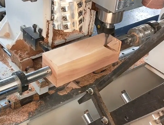
- Planing: Uses straight knives in a linear motion to flatten and dimension surfaces; milling is more flexible for complex profiles and 3D contours.
- Turning: The workpiece rotates and the tool is fed linearly; used mainly for cylindrical parts, while milling can produce planar and sculpted shapes.
Milling is especially suitable when precise contours, complex shapes, repeatable quality, or integration with computer-controlled production is required.
Basic Principles of Wood Milling
Wood milling relies on the interaction of four main elements: cutting tool, workpiece, relative motion, and chip formation. Understanding these principles is essential for accurate and efficient machining.
Cutting Motion and Feed Motion
The cutting motion is the rotation of the tool, and the feed motion is the movement of the workpiece or tool along the surface being machined. In conventional woodworking mills:
- The spindle carries the cutter and rotates at high speed.
- The table, fence, feed rollers, or CNC axes move the workpiece past the tool.
Chip thickness and surface finish depend on the combination of spindle speed, feed rate, and number of cutting edges.
Chip Formation in Wood
Wood is fibrous and heterogeneous. During milling, fibers are sheared and lifted. Cutting parameters and tool geometry must be chosen to:
- Reduce fiber tearing, especially around grain direction changes and defects.
- Maintain sufficient chip size for stable cutting without burning.
- Limit heat generation and tool wear.
Climb Milling and Conventional Milling
In wood machining, climb milling (down-milling) and conventional milling (up-milling) both occur:
Conventional milling (up-milling) starts with a chip thickness near zero and increases as the cutting edge exits. It can provide better control of tool engagement but may lead to more rubbing and heat.
Climb milling (down-milling) starts with maximum chip thickness and reduces to near zero, often providing cleaner cuts on some materials but requiring stable workpiece support and suitable equipment to avoid pull-in.
Types of Wood Milling Machines
Wood milling can be performed on various machines, from hand-fed routers to fully automated CNC machining centers. Each machine type has a typical application range, capacity, and level of precision.
| Machine Type | Typical Features | Typical Uses |
|---|---|---|
| Router (handheld) | Portable, high-speed spindle, uses collet-held bits | Edge profiling, grooves, template routing, on-site adjustments |
| Router table / Shaper | Stationary spindle, table support, fences, power feed (optional) | Moldings, joinery, repeatable edge work, small batch production |
| Spindle moulder (shaper) | Larger spindle, interchangeable cutter blocks, tilting spindle on some models | Heavy moldings, door frames, window profiles, complex edge shapes |
| Planer-moulder | Multiple heads, infeed/outfeed rollers, high throughput | Dimensioning and profiling boards, flooring, siding, structural components |
| CNC router | Computer-controlled axes, vacuum table, tool changer (often) | Nesting of panels, 2D and 3D contouring, cabinet parts, signage |
| CNC machining center | Multi-axis control, integrated drilling and milling, probing | Complex components, high-precision joinery, multi-face machining |
Common Wood Milling Operations
Wood milling includes a wide set of operations that shape surfaces, edges, and internal features. These operations can be combined in process sequences to achieve final part geometry.
Face Milling and Surface Planing
Face milling produces flat or slightly contoured surfaces across the face of a board or panel. It is used to:
- Flatten bowed or twisted stock within the capacity of the machine.
- Improve surface quality before finishing or bonding.
- Achieve consistent thickness when part of a multi-step process.
Edge Milling and Profiling
Edge milling shapes the edges of boards or panels with straight or profiled cutters. Applications include:
- Square or bevelled edges for panel joining.
- Decorative moldings such as ogee, round-over, and cove.
- Functional profiles for flooring, siding, and frame components.
Grooving, Slotting, and Rebating
Slots and grooves are machined into the surface or along the edge of workpieces. Typical uses are:
- Grooves for panels in frame-and-panel construction.
- Rebates (rabbets) for glass, backs, or edge joints.
- Dados for shelves, dividers, and structural joints.
Joint and Connection Milling
Milling is widely used to create joinery:
- Mortises and tenons (via dedicated jigs or CNC programs).
- Finger joints, dovetails, and box joints with specialized cutters or templates.
- Doweling holes and slots for connectors in panel and furniture systems.
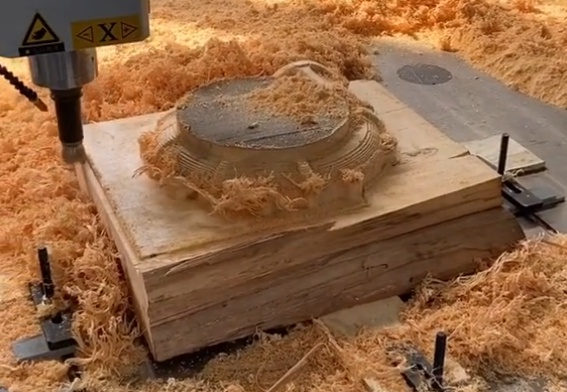
Contour and 3D Milling
CNC routers and machining centers can perform contour milling and 3D machining, allowing:
- Curved edges and irregular profiles.
- 3D reliefs, carvings, and ergonomic shapes.
- Complex intersecting geometries for furniture and architectural elements.
Wood Milling Tools and Tooling Systems
Tool selection directly affects surface quality, accuracy, productivity, and tool life. Wood milling uses both solid tools and assembled tool bodies with replaceable cutting edges.
Common Types of Cutting Tools
Key tool categories include:
- Router bits (straight, spiral, profile): used in routers and CNC machines.
- Cutterheads for spindle moulders and planers: often with multiple knives or inserts.
- End mills and drills adapted for wood: used mostly in CNC machining centers.
Tool Materials and Cutting Edges
Typical cutting materials are:
- High-speed steel (HSS): common for softwoods, easy to sharpen; used when cutting forces are moderate.
- Tungsten carbide (solid or brazed): provides higher wear resistance, especially for abrasive composites and hardwoods.
- Carbide inserts: mounted in cutterheads for consistent geometry and quick replacement.
Tool Geometry for Wood Milling
Wood responds strongly to cutter geometry. Important parameters include:
- Rake angle: affects chip flow and cutting forces.
- Clearance angle: prevents rubbing and overheating behind the cutting edge.
- Helix angle (for spiral tools): influences chip evacuation and edge quality.
Tools for cross-grain milling and end-grain cutting often use geometries that support fibers and reduce tear-out, such as shear-cutting designs and optimized rake angles.
Key Milling Parameters for Wood
Correct cutting parameters are essential to control quality, productivity, and tool life. Important variables include spindle speed, feed rate, depth of cut, and chip load.
| Parameter | Typical Range | Remarks |
|---|---|---|
| Spindle speed | 8,000–24,000 rpm (routers) / 4,000–12,000 rpm (spindle moulders) | High speed improves finish but increases heat; adjust by tool diameter. |
| Feed speed | 3–40 m/min for many operations, higher in high-speed lines | Higher feed increases output but may reduce surface quality. |
| Depth of cut (axial) | 0.5–6 mm in fine milling, higher in roughing | Deep passes increase load; multiple passes often preferred for precision. |
| Chip load per tooth | 0.05–0.40 mm/tooth (depending on tool and material) | Must be high enough to avoid rubbing but low enough to maintain edge quality. |
Feed Rate and Chip Load
Feed rate is calculated from spindle speed, number of cutting edges, and chip load per tooth. If chip load is too low, the tool rubs and overheats; if it is too high, surface defects and excessive tool stress can occur.
Depth of Cut and Step-Over
Depth of cut along the tool axis and step-over across the surface define how much material is removed per pass. For finishing, smaller depths and step-overs produce finer surfaces. For roughing, higher removal rates are used within the mechanical limits of the machine, tool, and workholding.
Materials Suitable for Wood Milling
Wood milling is applied to a wide range of wood-based materials. Each material type has specific considerations regarding cutting forces, edge quality, and tool wear.
Solid Wood
Solid wood species differ in density, hardness, and fiber structure. Important aspects include:
- Softwoods (e.g., pine, spruce): generally easier to mill but may exhibit resin build-up on tools.
- Hardwoods (e.g., oak, beech, maple): require sharper tools and often benefit from carbide edges.
- Grain orientation: cross-grain and end-grain cutting require attention to cutter geometry and feed direction to avoid tear-out.
Wood-Based Panels
Wood milling is intensively used for panel processing:
- Plywood: cross-laminated layers improve stability; sharp tools and correct chip load limit veneer splintering.
- MDF (medium-density fiberboard): homogeneous material, easy to machine but abrasive and prone to edge swelling without proper sealing.
- Particleboard: requires carbide tooling and optimized cutting conditions to control chip breakout at edges.
Laminated and Coated Boards
Decorative and functional coatings require clean edges without chipping. Strategies include:
- Use of compression spirals or special scoring tools.
- Appropriate support and clamping near the cut line.
- Balanced parameters to minimize vibration and tear-out.
Workholding and Fixturing
Stable workholding prevents chatter, dimensional errors, and kickback. Methods vary by machine type and part geometry.
Mechanical Clamping
Common methods include:
- Vises, clamps, and stops on tables or jigs.
- Feeding systems with infeed and outfeed rollers in moulders.
- Dedicated fixtures for repeatable positioning in batch production.
Vacuum and Specialized Fixtures
CNC routers and panel-processing equipment often use vacuum tables or pods. Advantages include:
- Fast clamping and unclamping for nested parts.
- Unobstructed access to surfaces for multi-side machining.
- Reduced risk of damage from mechanical clamps.
Surface Quality and Accuracy in Wood Milling
Surface finish and dimensional accuracy are central to functional, aesthetic, and assembly requirements.
Factors Affecting Surface Finish
Surface quality in wood milling is influenced by:
- Tool sharpness and geometry.
- Spindle speed, feed rate, and depth of cut.
- Machine rigidity and vibration control.
- Material properties, including moisture content and grain orientation.
Tolerances and Dimensional Control
Wood is hygroscopic and changes dimensions with moisture variations, so tolerances must consider both machining accuracy and dimensional stability over time. Techniques to improve control include:
- Conditioning stock to stable moisture content before milling.
- Using reference surfaces and fixture design to control location.
- Applying calibrated measuring tools and reference parts for setup.
Common Issues and Considerations in Wood Milling
Wood milling involves specific issues related to the material structure and process characteristics. Recognizing these helps in selecting suitable tools and parameters.
Surface Tear-Out and Splintering
Tear-out occurs when wood fibers are torn rather than cleanly cut, especially in cross-grain or around knots. To reduce tear-out:
- Use sharp, shear-cutting tools and appropriate cutter geometry.
- Adjust feed direction relative to grain orientation where possible.
- Limit depth of cut and use multiple passes for critical surfaces.
Tool Wear and Heat Buildup
Abrasive materials, resins, and high speeds cause tool wear and heat buildup. This affects surface quality and can result in burning marks. Mitigating steps include:
- Selection of carbide or suitable tool materials for abrasive boards.
- Regular cleaning to remove resin deposits.
- Better chip evacuation and adequate chip load to prevent rubbing.
Dimensional Changes Due to Moisture
After milling, wood can shrink or swell. Design and process planning must account for:
- Moisture content at time of machining.
- Expected service environment humidity.
- Grain direction and part geometry in relation to movement.
Safety in Wood Milling
Wood milling involves high-speed rotating tools and feed mechanisms. A systematic approach to safety is required to reduce the risk of injury and damage.
Personal Protective Equipment (PPE)
Typical PPE for wood milling includes:
- Eye protection (safety glasses or face shield).
- Hearing protection due to high noise levels.
- Respiratory protection when dust extraction is insufficient.
- Close-fitting clothing and suitable gloves where appropriate, with consideration of entanglement risks.
Machine Guards and Safety Devices
Machines should be equipped with:
- Tool and fence guards to prevent direct contact with rotating cutters.
- Emergency stop buttons within easy reach.
- Anti-kickback devices and appropriate feed rollers where applicable.
Safe Operating Practices
Safe milling requires:
- Correct setup and testing before full production.
- Stable workholding and avoidance of loose parts near cutters.
- Routine inspection and maintenance of machines, guards, and dust extraction systems.
Applications of Wood Milling
Wood milling supports a wide range of industries and products, from small craft work to high-volume building components.
Furniture and Cabinetry
In furniture and cabinet production, milling is used to:
- Produce structural frames, panels, and decorative elements.
- Machine joinery and hardware mounting points.
- Create precise mating surfaces for assembly and finishing.
Architectural Millwork
Architectural elements rely heavily on wood milling processes:
- Profiles for moldings, baseboards, and casings.
- Door and window components with precise joint geometry.
- Custom trims, handrails, and panel systems.
Construction and Structural Components
In construction-oriented production, milling supports:
- Flooring, siding, and decking with interlocking profiles.
- Engineered wood elements with machined interfaces.
- Timber framing elements with milled joints and notches.
Process Planning and Workflow for Wood Milling
Effective use of wood milling requires planning the sequence of operations, machine usage, and quality checks.
From Rough Stock to Finished Part
A typical workflow might include:
- Selection and conditioning of material (moisture control, inspection).
- Primary cutting and rough dimensioning.
- Milling for accurate thickness, width, and surface quality.
- Edge profiling, joinery milling, and final machining details.
- Quality inspection and preparation for finishing or assembly.
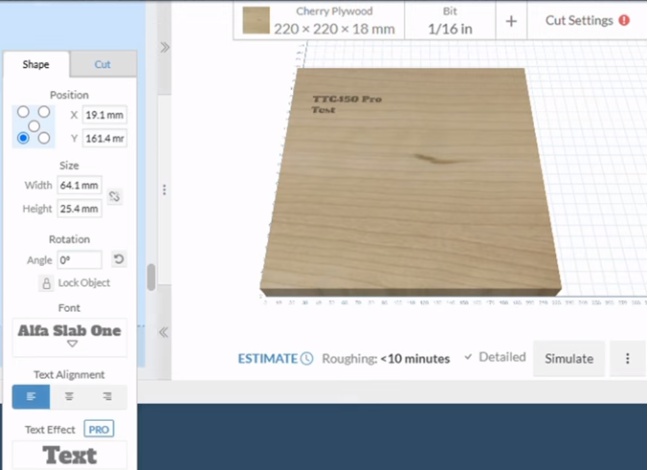
Integration with Digital Design and CNC
For CNC-based milling, workflow aspects include:
- CAD modeling of parts and assemblies.
- CAM programming for toolpaths, tools, and parameters.
- Setup of fixtures, zero points, and tool length measurement.
- Simulation and trial runs before full production.
Maintenance of Wood Milling Equipment and Tools
Regular maintenance helps maintain consistent quality and extend equipment life.
Machine Maintenance
Key tasks include:
- Cleaning of chips and dust from machine surfaces and mechanisms.
- Lubrication of bearings, guides, and feed systems as specified by the manufacturer.
- Checking spindle runout, alignment of fences and guides, and condition of belts or couplings.
Tool Care and Sharpening
Tool maintenance involves:
- Periodic inspection for wear, chips, and imbalance.
- Proper sharpening or replacement at defined intervals.
- Storage in protective racks or holders to prevent edge damage.
How to Choose a Wood Milling Method
Selecting the appropriate milling method and equipment depends on production scale, accuracy requirements, material types, and part complexity.
Key Selection Considerations
Important aspects when choosing milling approaches include:
- Required tolerances and surface finish.
- Batch size and production frequency.
- Available machinery, tooling, and technical skills.
- Part geometry, including need for 3D shapes or multi-face machining.
Balancing these factors allows a systematic choice between manual router operations, spindle moulder setups, moulder lines, or CNC-based machining, ensuring reliable, repeatable milling outcomes.