CNC engraving and CNC milling are closely related subtractive machining processes, but they are optimized for different tasks, geometry scales and surface requirements. Understanding how they differ in process characteristics, machine configuration, tooling, parameters, and application scope is essential for selecting the most suitable method for a given job.
Fundamental Definitions and Concepts
CNC Engraving
CNC engraving is a precision material removal process used primarily to create shallow, narrow, and fine features such as letters, logos, serial numbers, textures and micro-channels. Typical characteristics include:
- Small cutting depth per pass, often between 0.02–0.50 mm
- Very small tool diameters (e.g., 0.1–3 mm) and fine tip radii
- High spindle speeds (often above 20,000 rpm) to maintain cutting speed with small tools
- Focus on detail reproduction, edge sharpness and visual clarity
Engraving can be performed on metals, plastics, wood, glass, and composite materials, as long as the cutting parameters and tooling are matched to the material.
CNC Milling
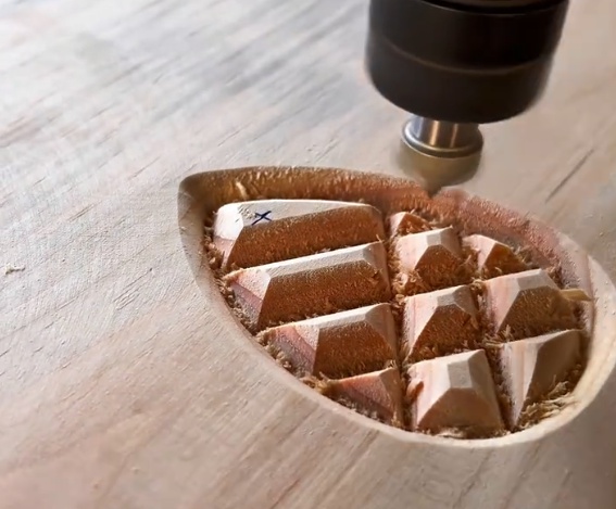
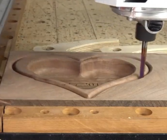
CNC milling is a broader machining process used to remove larger volumes of material and generate complex 2D and 3D shapes such as pockets, slots, contours, planar faces and freeform surfaces. Typical characteristics include:
- Greater cutting depth and width per pass
- Larger tool diameters (e.g., 3–25 mm and beyond)
- Moderate to high spindle speeds depending on material and tool size
- Focus on dimensional accuracy, geometric complexity and productivity
Milling operations include facing, contouring, pocketing, drilling, tapping, and 3D surface machining on a wide variety of materials, especially metals and engineering plastics.
Process Characteristics and Mechanical Differences
Material Removal Mechanism
Both engraving and milling use rotating tools to remove material via chip formation. The primary differences lie in the scale and distribution of the material removal:
CNC engraving uses:
- Very small engagement of tool into the workpiece (low chip thickness)
- Higher rotational speeds to maintain recommended cutting speeds for small diameters
- Tool paths that follow fine contours, fonts and patterns
CNC milling uses:
- Larger engagement (depth and width of cut) and higher material removal rates
- Tool paths optimized for roughing and finishing, with separate strategies
- Tool sizes and geometries chosen to balance productivity and accuracy
Machine Structure and Rigidity
Many engraving machines are derivatives of light-duty CNC routers or purpose-built engraving centers. They often feature:
- High-speed spindle units (air-cooled or water-cooled)
- Relatively light machine frames and smaller working envelopes
- High-resolution motion systems to achieve small incremental movements
Dedicated milling machines, particularly for metal cutting, typically have:
- Heavier cast-iron or welded steel frames for rigidity
- Higher power spindles with greater torque for larger tools
- Robust linear guides and ball screws to resist cutting forces
As a result, milling machines handle higher cutting forces and larger tools better, while engraving machines excel at small, precise motions with lower cutting loads.
Tooling and Geometry Differences
Engraving Tools
Engraving tools are specialized for narrow, precise features. Common types include:
- V-bit (conical) engraving cutters with angles such as 15°, 20°, 30°, 45°, 60°, 90°
- Micro end mills with diameters down to 0.1 mm or less
- Ball nose engraving cutters for shallow 3D textures or reliefs
Typical parameters of engraving cutters include tip radius, included angle, effective cutting length and shank diameter. The small tip radius allows sharp internal corners and fine lettering.
Milling Tools
Milling tools cover a broad range of shapes:
- Flat end mills for pocketing and facing
- Ball nose end mills for 3D surface generation
- Corner radius end mills for improved strength and surface quality
- Face mills and shell mills for planar surfaces
Milling tools are selected based on material (carbide, HSS, coated carbide), flute number, helix angle, and diameter to optimize chip evacuation, strength and surface finish.
Parameter Comparison and Typical Ranges
| Parameter | CNC Engraving (Typical) | CNC Milling (Typical) |
|---|---|---|
| Tool diameter | 0.1–3 mm | 3–25 mm (and above) |
| Spindle speed | 20,000–60,000 rpm (depending on tool and material) | 3,000–20,000 rpm (depending on tool and material) |
| Depth of cut per pass | 0.02–0.50 mm | 0.5–10 mm or more (material and tool dependent) |
| Feed rate | 100–2,000 mm/min (fine detail work) | 300–10,000 mm/min (roughing and finishing) |
| Typical feature size | 0.1–2 mm line width, small characters and logos | Slots, pockets and contours from a few millimeters to hundreds of millimeters |
| Main objective | Fine detail, clarity and surface appearance | Material removal rate, dimensional accuracy and surface finish |
These ranges are indicative and depend on machine capability, material properties, tool specifications and required quality.
Accuracy, Surface Finish and Detail Resolution
Dimensional Accuracy
Both processes can achieve high dimensional accuracy when machines are properly calibrated and maintained. Milling machines designed for precision metal cutting often reach tolerances such as ±0.01–0.02 mm for general work and tighter for high-precision parts. Engraving machines targeting small features may emphasize positional repeatability and fine incremental steps for accurate character spacing and pattern placement.
Surface Finish
Engraving often operates with smaller tools and lighter loads, which can yield smooth, visually appealing surfaces, particularly on softer materials. The surface texture may depend heavily on feed rate, step-over, tool geometry and material hardness.
Milling can reach very low surface roughness values when using finishing passes with appropriate step-over and tool selection. Ball nose tools and high-speed finishing strategies are commonly used to achieve fine finishes on molds and complex 3D surfaces.
Detail Resolution
Engraving is better suited to very fine detail due to tool geometry and small diameters. Fonts below a few millimeters in height, intricate logos and micro-features can be reliably produced with engraving tools and high-speed spindles. Milling can also handle small features, but tool strength, runout and machine rigidity may limit minimum tool sizes on some milling centers.
Material Compatibility
Metals
Both engraving and milling are used on metals such as aluminum, brass, copper, steel and stainless steel. Important considerations include:
- For engraving on hard metals, rigid setups, stable clamping and accurate tool runout control are important to avoid tool breakage.
- For milling, tool selection and cutting parameters must be matched to the metal type and hardness to prevent chatter and excessive tool wear.
Non-metals
Engraving is widely used on plastics (acrylic, ABS, polycarbonate), wood, laminates, enamel-coated plates and some stones. Milling is also common for plastics and wood in applications such as molds, fixtures and prototypes. In brittle materials like glass or certain ceramics, specialized engraving tools and techniques are required to minimize chipping.
Machine Types and Axis Configurations
Engraving Machines
Common engraving machine configurations include:
- Desktop 3-axis engraving machines for small plates, tags and electronic panels
- Medium-size routers with high-speed spindles for sign making and decorative panels
- Special-purpose engraving centers with automatic tool changers and vision systems for precise alignment
These machines focus on high-speed, low-force operations and may prioritize compact size and ease of use.
Milling Machines
Milling machines range from small vertical machining centers to large gantry mills. Typical axis configurations include:
- 3-axis mills for general prismatic parts
- 4-axis mills for rotary or indexed machining of more complex geometries
- 5-axis mills for complex 3D shapes and multi-face machining in a single setup
Higher-axis machines are commonly used in mold and die making, aerospace parts, medical implants and other complex components.
Application Scope and Typical Use Cases
Typical CNC Engraving Applications
Engraving is commonly used for:
- Serial numbers, QR codes, barcodes and identification marks on metal and plastic parts
- Logos, brand names and decorative patterns on consumer products
- Nameplates, instrument panels, labels and control panels
- Textured surfaces, fine reliefs and shallow 3D patterns
Typical CNC Milling Applications
Milling is widely used in manufacturing for:
- Machining structural components, brackets, housings and covers
- Mold and die manufacturing for injection molding, die casting and stamping
- Prototyping and small batch production of mechanical parts
- Preparation of fixture plates, jigs and tooling components
In many cases, parts may be milled first to form the main geometry, and engraving is then used to add markings, text or logos.
Programming, CAM and Toolpath Strategies
CAD/CAM Workflow
Both engraving and milling rely on CAD models and CAM software, but the approach differs slightly:
- Engraving often starts from vector graphics, fonts or 2D drawings. CAM software converts these into toolpaths that follow lines and curves at a defined depth.
- Milling typically uses 3D solid or surface models and applies toolpath operations such as roughing, semi-finishing and finishing with specified step-overs and step-downs.
Toolpath Types
Common toolpath strategies for engraving include:
- Outline tracing of fonts and curves
- Pocket engraving for filled characters or shapes
- 3D relief engraving using height maps or 3D models
For milling, typical strategies include:
- Facing passes to create reference planes
- 2D pocketing and contouring
- 3D surface finishing with parallel, radial, or spiral paths
Clamping, Fixturing and Workpiece Stability
Engraving Fixturing
Engraving operations often involve thin plates, small tags or pre-finished parts. Clamping solutions must avoid distortion and surface damage. Common approaches include:
- Vacuum tables for thin sheets
- Low-profile mechanical clamps at the edges
- Custom fixtures with locating pins and soft jaws for repeat positioning
Milling Fixturing
Milling involves more substantial cutting forces. Vises, T-slot clamps, modular fixturing systems and dedicated fixtures are used to secure the workpiece. Correct fixturing is essential to maintain dimensional accuracy and avoid vibration and deflection.
Selection Criteria: When to Use Engraving or Milling
Feature Size and Geometry
Engraving is preferred when:
- Feature widths are very small (for example less than 1 mm)
- High visual quality of text and logos is required
- Depth is shallow and uniform
Milling is preferred when:
- Material volume to remove is large
- Component requires slots, pockets, steps and complex shapes
- Structural strength and precise dimensional relationships are critical
Machine Capability and Tooling Availability
Selection also depends on available machines and tooling. A high-speed engraving machine with suitable small-diameter tools will be more efficient for fine text than a large milling center. Conversely, roughing a large pocket on an engraving machine may be inefficient and may exceed the machine’s rigidity and power capacity.
Cost, Efficiency and Production Considerations
Cycle Time and Productivity
Milling is usually more efficient for bulk material removal due to larger tools and higher feed rates. Engraving uses smaller tools and lighter passes, so cycle time is often dominated by fine detail tracing. For products that require both structural machining and marking, a common approach is to mill the part first and then perform engraving in a separate operation or on the same machine if it supports engraving tools and parameters.
Tool Wear and Maintenance
Engraving tools with very fine tips are sensitive to wear and breakage, especially in hard metals. Stable process parameters and correct toolpath strategies help extend tool life. Milling tools face higher cutting forces and require proper selection of tool material, coatings and cooling methods to manage wear and maintain surface quality.
Integration: Combining Engraving and Milling
Single-Machine Approach
Many modern CNC milling machines can perform engraving operations by using small-diameter tools and suitable post-processors. This allows machining and marking in one setup, ensuring alignment between features and markings. The main requirements are sufficient spindle speed, precision and runout control for small tools.
Dedicated Engraving After Milling
In some workflows, parts are milled on heavy-duty machining centers and then transferred to specialized engraving machines for final marking. This approach can be beneficial when high throughput milling is needed, and detailed decorative or identification features must be applied with different tooling or under specific conditions.
Summary of Key Differences and Considerations
| Aspect | CNC Engraving | CNC Milling |
|---|---|---|
| Main purpose | Fine detail, text, logos, shallow reliefs | General shaping, pockets, contours, 3D surfaces |
| Tool scale | Very small, fine-tipped tools | Small to large end mills, face mills |
| Spindle speed | Typically higher to support small tools | Moderate to high depending on tool size |
| Depth of cut | Shallow, precise cuts | Shallow to deep cuts for roughing and finishing |
| Machine rigidity | Optimized for light cutting forces and precision | Optimized for higher cutting forces and productivity |
| Typical features | Serial numbers, nameplates, patterns | Mechanical parts, molds, structural components |
By evaluating feature size, material, required surface quality, production volume and available equipment, it is possible to decide whether CNC engraving, CNC milling, or a combination of both will yield the most efficient and precise result for a given application.