What Is CNC Engraving
CNC engraving is a subtractive machining process that uses computer numerical control to create permanent markings, text, logos, textures, and fine details on workpieces by removing small amounts of material. Unlike general-purpose milling, engraving focuses on shallow, narrow features with high visual or functional precision.
Motion is controlled along programmed toolpaths, usually in 2D or 2.5D, while depth is precisely regulated. Machines can be CNC routers, milling machines, laser engravers, or dedicated engraving machines. The goal is consistent, repeatable detail at controlled depth and width.
Core Components of a CNC Engraving System
A CNC engraving setup consists of mechanical, electrical, and software components working together. Understanding each part helps in configuration, optimization, and problem diagnosis.
Machine Types
- CNC routers with high-speed spindles for wood, plastics, composites, and soft metals
- CNC milling machines for higher rigidity and metal engraving
- Dedicated engraving machines with light gantries and very high spindle speeds
- Laser engravers and cutters for non-contact engraving and marking
Selection depends on material hardness, required detail, throughput, and available budget.
Spindle and Motion System
The spindle provides rotational power for mechanical engraving tools. Key parameters include power, speed range, runout, and bearing quality. For fine engraving, high RPM and low runout are critical to obtain clean, narrow lines.
The motion system (linear guides, ballscrews or belts, motors, and drives) must provide adequate stiffness, accuracy, and repeatability. Backlash and vibration directly affect engraving quality and legibility of small characters.
Control, Electronics, and Software
The CNC controller interprets G-code and drives axes and spindle. Common options are PC-based controllers, standalone industrial controllers, and integrated motion systems. Stable communication and reliable homing are fundamental for repeatable depth and position.
Software includes CAD (design), CAM (toolpath generation), and machine control software. Consistency across the workflow avoids scaling mismatches, incorrect units, and post-processor issues.
Engraving Methods and Processes
CNC engraving can be achieved using different physical methods. Each method has distinct capabilities and limitations regarding materials, detail level, and surface finish.
Mechanical Engraving
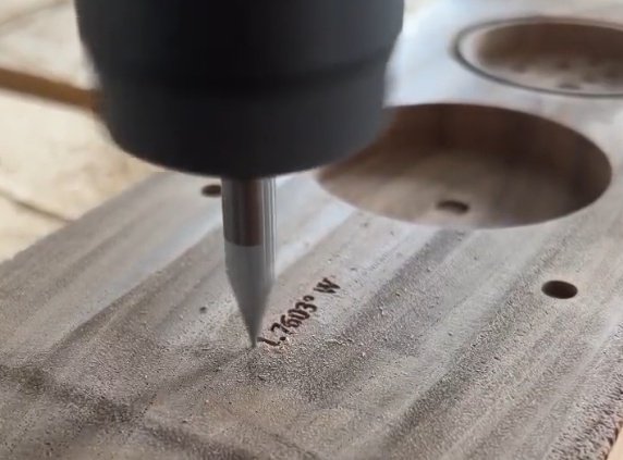
Mechanical engraving uses rotating or oscillating tools to cut grooves into the workpiece. It is suited for metals, plastics, wood, and many composites. Typical tools include V-bits, ball-nose end mills, and drag engravers. Depth and tool geometry determine line width and profile.
Laser Engraving
Laser engraving employs a focused laser beam to vaporize, melt, or discolor material. It enables fine detail and very small text on a wide range of materials (metals, plastics, organics, ceramics, coated surfaces). Depth is generally shallower than mechanical engraving but can be sufficient for codes, labels, and decorative patterns.
Rotary vs Drag Engraving
Rotary engraving uses a powered spindle to rotate the tool, suitable for cutting deeper grooves and harder materials. Drag engraving uses a spring-loaded diamond or carbide tip that is dragged across the surface without rotation, primarily for very shallow marking on softer materials, coated panels, and anodized aluminum.
2D, 2.5D, and 3D Engraving
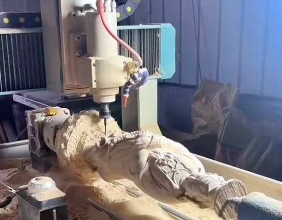
2D engraving involves constant depth across the design, with movement primarily in X and Y. 2.5D engraving adjusts depth for different features while still using standard planar operations. 3D engraving (relief engraving) follows complex 3D surfaces and height maps, requiring more advanced CAM strategies and higher-resolution toolpaths.
Materials for CNC Engraving
Material properties influence tool selection, spindle speed, feed rate, depth per pass, cooling, and workholding. Proper pairing of technique and material ensures clean edges and controlled wear.
Metals
Common metals for CNC engraving include aluminum, brass, copper, stainless steel, tool steel, and precious metals. Aluminum and brass are relatively easy to engrave with carbide tools at high spindle speeds. Stainless and hardened steels require lower cutting speeds, rigid fixturing, and often coated tools.
Metal engraving is used for nameplates, serial numbers, functional labels, molds, dies, and aesthetic patterns. Coolant or air blast helps prevent built-up edge and maintain tool life.
Plastics and Composites
Plastics such as acrylic, polycarbonate, ABS, PVC, and engineering polymers can be engraved with sharp tools and higher spindle speeds. Heat buildup must be controlled to avoid melting, burrs, and surface whitening. Chip evacuation is important to keep fine details clear.
Composite materials, including laminates and fiber-reinforced plastics, demand careful tool selection to minimize delamination and fiber pull-out. Engraving is often used for control panels, signs, and identification plates.
Wood and Wood-Based Panels
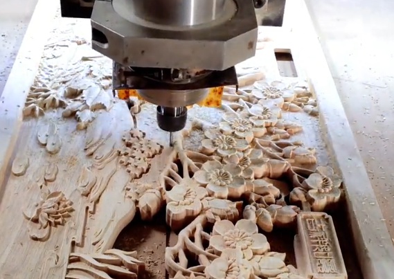
Wood, MDF, plywood, and engineered panels are commonly engraved with CNC routers. Grain direction, density variations, and resin content affect cut consistency. Tools designed for wood, with adequate chip clearance and sharp edges, provide clean lines and minimal fuzz.
Applications include decorative panels, logos, inlays, signage, and personalized items. Dust extraction is important to maintain accuracy and operator safety.
Other Materials
Additional materials for CNC engraving include glass, stone, ceramics, and coated surfaces. These typically require specialized tools (diamond-tipped, sintered tools) or laser systems. Non-metallic hard materials often demand slower feeds and high rigidity to avoid tool damage and chipping.
CNC Engraving Tools and Tooling Parameters
Tool geometry and material govern surface finish, line width, achievable detail, and tool life. Correct parameter selection (speed, feed, and depth) is essential for predictable results.
Common Engraving Tool Types
| Tool Type | Geometry | Typical Use | Key Advantages |
|---|---|---|---|
| V-bit (V-cutter) | Conical with included angle (10°–120°) | Text, fine lines, V-carving, chamfers | Variable line width by depth, crisp edges |
| Ball-nose end mill | Spherical tip, various diameters | 3D relief engraving, smooth contours | Good surface finish on 3D surfaces |
| Flat end mill (micro) | Flat tip, small diameters (e.g., 0.2–2 mm) | Small pockets, rectangular grooves | Accurate flat-bottom features |
| Drag engraver | Spring-loaded diamond or carbide tip | Shallow marking on coated metals, plastics | No spindle power required, quiet operation |
| Laser beam (optics) | Focused spot (tens to hundreds of microns) | Fine marking, coding, shallow surface textures | Non-contact, high detail, minimal tool wear |
Tool Materials and Coatings
Carbide tools are favored for most mechanical engraving due to hardness and wear resistance. High-speed steel may be used for softer materials but wears faster in abrasive or hard metals. Coatings such as TiN, TiAlN, and DLC reduce friction and extend tool life in metals, especially at higher speeds.
Diamond tools are used for drag engraving and very fine finishing on hard or brittle materials, providing a polished groove with minimal burrs.
Tool Geometry and Line Width
V-bit geometry directly influences line width at a given depth. Narrower included angles allow finer lines but are more fragile; wider angles produce more robust tips but wider cuts at the same depth. Ball-nose and flat tools have line width determined mainly by tool diameter and stepover.
To achieve consistent visual thickness for fonts and logos, depth control must be tightly maintained and matched to tool geometry. CAM software can compute variable depth to achieve uniform stroke width using V-carving algorithms.
Spindle Speed, Feed Rate, and Depth of Cut
Engraving uses lighter cuts than standard milling. Typical practice is higher spindle speeds combined with moderate feeds and shallow depth increments to avoid tool breakage and surface damage.
For a given tool and material, the main parameters are:
- Spindle speed (RPM)
- Feed rate (mm/min or in/min)
- Depth per pass (mm or in)
Parameter optimization balances cutting load, vibration, heat, and time. Test cuts and manufacturer recommendations provide starting points, followed by fine-tuning based on observed results.
Feeds, Speeds, and Depth Guidelines
Specific parameters depend on machine rigidity, tool length and diameter, material hardness, and coolant. However, structured guidelines are useful as a baseline.
| Material | Tool Type / Size | Spindle Speed (RPM) | Feed Rate (mm/min) | Depth per Pass (mm) |
|---|---|---|---|---|
| Aluminum (soft alloy) | V-bit 60°, 0.2 mm tip | 18,000–24,000 | 300–800 | 0.05–0.15 |
| Brass | V-bit 45°, 0.15 mm tip | 18,000–28,000 | 300–700 | 0.03–0.10 |
| Stainless steel | Carbide V-bit 60°, 0.25 mm tip | 10,000–18,000 | 120–400 | 0.02–0.08 |
| Acrylic | V-bit 60°, polished flute | 18,000–24,000 | 400–900 | 0.05–0.20 |
| Hardwood | V-bit 90° | 14,000–22,000 | 600–1,500 | 0.2–0.7 |
| Coated aluminum (drag) | Diamond drag tip | Spindle off or low | 300–600 | Spring pressure defines depth |
These values are starting ranges only. Actual parameters should be validated on the specific machine. If chatter, burrs, or tool wear occur, adjustments to speed, feed, or depth are required.
Workholding and Machine Setup for Engraving
Engraving performance depends heavily on secure workholding and precise machine setup. Even small movements or tilts can change engraving depth and appearance.
Workpiece Fixturing Methods
Common workholding methods for engraving include vises, clamps, vacuum tables, double-sided tape or adhesive, dedicated fixtures, and rotary or 4th-axis fixtures for cylindrical parts. The chosen method must prevent lifting, lateral movement, and vibration under light cutting forces.
Thin and flexible parts can easily deflect, resulting in inconsistent depth. Backing plates, sacrificial boards, or vacuum fixtures help maintain flatness during engraving.
Surface Tramming and Leveling
When engraving shallow features, even minor deviations in surface flatness or machine tram can cause variable line width. Tramming the spindle (aligning it perpendicular to the table) and surfacing the spoilboard or fixture improve consistency.
For small or critical parts, probing or mapping the surface allows height compensation. This is particularly important for PCBs or large panels where thickness variation is significant.
Zeroing and Tool Length Setting
Accurate setting of the workpiece zero and tool length offset is essential. Common methods include using a touch plate, feeler gauges, or probing systems. The Z-zero can be set at the workpiece surface or at a reference plane depending on the CAM setups.
Tool changes must be managed carefully. Any variation in tool length or collet seating without recalibration can alter engraving depth, affecting line width and visibility.
CAM Workflow for CNC Engraving
Engraving requires a well-structured CAD/CAM workflow to convert designs into reliable toolpaths that the CNC machine can execute.
Designing Text, Logos, and Patterns
CAD or vector design software is used to create the geometry of text, logos, and patterns. Vector-based formats (e.g., DXF, SVG) are preferred for precise lines and arcs. Fonts should be selected with engraving suitability in mind; single-line fonts or fonts optimized for engraving often produce better results for small text.
Closed contours, self-intersections, and duplicate lines should be corrected before importing to CAM to avoid unwanted tool movements or overcutting.
Toolpath Strategies
CAM software offers various engraving strategies, including:
- Profile engraving along vector lines
- V-carving with variable depth for uniform visual stroke width
- Pocketing for filled regions and bold characters
- 3D relief toolpaths using ball-nose tools for sculpted surfaces
Lead-in and lead-out moves reduce witness marks at the start and end of paths. Overlap between passes, stepover, and stepdown determine surface quality and machining time.
Post-Processing and G-code
After toolpath generation, post-processing converts CAM data into machine-ready G-code. The correct post-processor must be chosen for the specific controller to ensure proper codes for tool changes, spindle control, coolant, and coordinate systems.
Before production, simulation helps verify paths, detect collisions, and confirm that depths and directions match expectations. A dry run above the workpiece is often used as a final check.
Quality, Accuracy, and Repeatability in Engraving
Engraving quality is judged by line sharpness, depth uniformity, legibility, alignment, and overall aesthetic consistency. Achieving and maintaining quality requires attention to mechanical, tooling, and process variables.
Factors Affecting Engraving Quality
Critical factors include machine rigidity, spindle runout, tool sharpness, workpiece flatness, accurate parameter selection, and stable fixturing. Any looseness or inaccuracy will appear as waviness, inconsistent depth, or blurred edges in the engraving.
Thermal expansion of the machine or workpiece can slightly shift dimensions during long runs. Temperature-stable environments and warm-up routines help maintain repeatability.
Burr Control and Surface Finish
Burr formation is common, especially in ductile metals and certain plastics. Tool sharpness, cutting direction, and feeds and speeds influence burr size. Deburring may be needed for functional or high-appearance parts.
For visible surfaces, achieving a uniform finish is important. Proper chip evacuation, coolant or air blast, and avoidance of recutting chips contribute to cleaner lines and a more consistent appearance.
Common Issues and Troubleshooting in CNC Engraving
Specific issues can degrade engraving results or reduce productivity. Identifying root causes enables systematic improvement and more reliable workflows.
Inconsistent Engraving Depth
Variable depth causes some parts of the design to be too shallow or too deep. Common causes are uneven workpiece surfaces, warped material, incorrectly set Z-zero, tool length inconsistencies, and machine bed not being level relative to the spindle.
Corrective actions include surfacing the spoilboard or fixture, using flat backing plates, probing for height compensation, verifying tram, and using consistent, calibrated tool length offsets.
Poor Edge Quality and Chatter
Chatter and rough edges indicate a combination of insufficient machine rigidity, excessive tool overhang, incorrect feeds and speeds, or dull tools. Reducing depth per pass, lowering feed rate, adjusting spindle speed, and using shorter or more rigid tooling can improve edge quality.
For hard materials, switching to coated carbide or more suitable geometries helps reduce cutting forces and improves line definition.
Tool Breakage and Excessive Wear
Fine engraving tools are fragile. Breakage can result from aggressive depth, excessive feed, improper entry moves, or unexpected workpiece movement. Wear can be accelerated by abrasive materials, inadequate lubrication, or incorrect cutting speeds.
Monitoring tool condition, establishing maximum passes per tool, and using parameter sets appropriate for the material reduce downtime and scrap.
Alignment and Registration Errors
Misalignment issues include designs not centered on the part, rotated engravings, or mismatch between front and back operations. These often stem from inaccurate workpiece zeroing, inconsistent fixturing, or neglecting reference edges.
Standardized reference points, dowel pins, dedicated fixtures, and clear setup documentation improve repeatability when producing the same engraved design repeatedly.
Safety and Maintenance in CNC Engraving
Safe operation and consistent maintenance protect operators, machines, and workpieces. Engraving often involves small chips, dust, and high spindle speeds.
Operator Safety Measures
Mechanical engraving requires guarding against moving parts, flying chips, and tool breakage. Safety glasses or face shields, hearing protection where needed, and proper machine enclosures are fundamental. Dust collection or local extraction is important when engraving wood, plastics, or composites.
Laser engraving demands appropriate protective eyewear for the specific wavelength, enclosure to prevent beam escape, interlocks, and ventilation or filtration to manage fumes and particulate emissions.
Routine Machine Maintenance
To maintain precision, regular checks and maintenance are required. Common practices include cleaning chips and dust from guides and screws, lubricating mechanical components per manufacturer instructions, inspecting belts or couplings for wear, checking spindle bearings for abnormal noise or play, and periodically verifying axis accuracy with test engravings.
Software and firmware updates for controllers and CAM packages should be managed carefully, with validation to ensure that post-processors and parameter sets remain compatible with established workflows.
Applications of CNC Engraving
CNC engraving is used across industrial, commercial, and custom production contexts wherever permanent, precise markings or decorative features are required.
Industrial and Functional Marking
Engraving supports part identification, traceability, and labeling in production environments. Examples include serial numbers, data plates, scales and graduations, panel labels, and functional symbols. Requirements often include legibility under harsh conditions, compatibility with regulatory standards, and resistance to wear.
Signage, Branding, and Personalization
Sign makers and branding specialists use engraving for logos, nameplates, architectural signage, and customized products. Materials range from metals and plastics to wood and composites, in both indoor and outdoor settings. Consistent branding elements and repeatable quality are important for series production.
Molds, Dies, and Tooling
In mold and die manufacturing, engraving is used to create part numbers, cavity identifiers, texture patterns, and functional markings within mold cavities and die surfaces. Requirements often include small text, high accuracy, and compatibility with subsequent finishing processes such as polishing.
Electronics and Panels
Control panels, instrument faces, PCBs, and electronic housings frequently rely on engraving for legends, symbols, and reference markings. Consistent character size, alignment with cutouts and components, and clear visual contrast are key considerations in these applications.
Planning a CNC Engraving Process
Effective planning improves output quality and reduces rework. A structured approach defines requirements, resources, and process parameters before machining begins.
Defining Requirements
Key requirements include material type and dimensions, desired engraving depth, line width, font size, visual contrast, surface finish, and production quantity. Environmental conditions, such as exposure to chemicals or outdoor use, influence choice of material and engraving method.
Selecting Equipment, Tools, and Parameters
Based on requirements, suitable machine type, tooling, workholding, and CAM strategy are selected. Parameters are initially set using guidelines and manufacturer data, then refined through sample runs. Documenting the final settings, tool identifiers, and fixture references enables consistent reproduction of the process.
Verification and Documentation
Test engravings on scrap or representative material are used to verify legibility, depth, and alignment. Measurement tools, such as optical comparators, microscopes, or depth gauges, may be used for critical features. The verified process is then documented with tool lists, setup instructions, and parameter sheets.
Conclusion
CNC engraving integrates precise motion control, appropriate tooling, and carefully tuned parameters to produce detailed markings and textures across a wide range of materials. By understanding machine components, tooling options, parameter selection, fixturing, and CAM workflows, users can achieve stable, repeatable engraving quality and meet demanding dimensional and aesthetic requirements.
Establishing standardized procedures for setup, parameter selection, verification, and maintenance supports dependable production and consistent results, whether for industrial marking, decorative work, or tooling applications.